Several audio connections are available on the on STM32H735G-DK board:
• The analog input line is connected to the WM8994ECS/R ADC through the blue audio jack (CN11).
• The analog output line is connected to the WM8994ECS/R DAC via the green audio jack (CN10).
• Two external speakers can be connected to the WM8994ECS/R via CN13 for the left speaker and CN12 for
the right speaker. The STM32H735G-DK board features one digital MP34DT05-A microphone (ST-MEMS
microphone). It is connected to the input digital microphone of the STM32H735IGK6Uand is managed by the
PDM functionality.
Limitation:
On the STM32H735G-DK board, SAI1 signals are sharing the same I/Os with SPI5 and UART7 signals. As a
consequence, when using SAI1 interface for the audio codec, the user must make sure that there is nothing
connected on STMod+ (1,2,3,4 pins), Pmod
™
(1,2,3,4 pins) and ARDUINO
®
(D10, D11, D12, D13 pins)
connectors.
DIGITAL microphone
The U33 on the STM32H735G-DK board is STMicroelectronics MP34DT05-A MEMS digital omnidirectional
microphone providing PDM (pulse density modulation) output. The microphone is supplied with a programmable
clock generated directly by the STM32H735IGK6U (SAI4_CK2 signal) or the audio codec (DMICCLK signal).
As an option, the microphone can be connected to U12 (Wolfson WM8994 audio codec device). In that
configuration, WM8994 also supplies the PDM clock to the microphone. Regardless of the microphone routing
(STM32H735IGK6U or WM8994 codec), the power can be supplied either by the 3V3 or the MICBIAS1 output of
the WM8994 codec device.
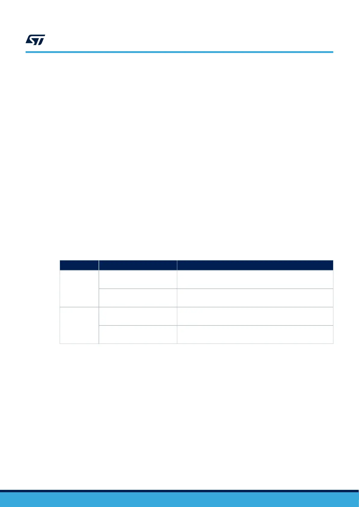
Table 8 shows the settings of all solder bridges associated with the digital microphone on the board.
Table 8. Digital microphone – Solder bridge configuration
Solder bridge
Setting
(1)
Configuration
SB40, SB39
SB38, SB28
SB40, SB39 OFF
SB38, SB28 ON
The PDM clock for the digital microphone is provided by the WM8994
codec.
SB40, SB39 ON
SB38, SB28 OFF
The PDM clock for the digital microphone is provided by the
STM32H735IGK6U MCU
SB36, SB37
SB36 OFF
SB37 ON
The power supply of the digital microphone is generated by the
WM8994 codec (MICBIAS1).
SB36 ON
SB37 OFF
The power supply of the digital microphone is 3V3
1. The default setting is in bold.
7.7
CAN FD
The STM32H735G-DK board supports three channels of CAN FD (Flexible data-rate CAN) compliant bus based
on 3V3 CAN transceiver.
Limitation:
On the STM32H735G-DK board, the CAN‑FD3 signals are sharing with SPI5 and UART7 signals. As a
consequence, when using CAN‑FD3 interface, the user must make sure that there is nothing connected on
STMod++ (1,2,3,4 pins), Pmod
™
(1,2,3,4 pins) and ARDUINO
®
(D10, D11, D12, D13 pins) connectors.
UM2679
CAN FD
UM2679 - Rev 1
page 17/42

 Loading...


