MCU port Signal name CN19 pin number Signal name MCU port
PB8 LCD_B6 33 34 GND -
PB9 LCD_B7 35 36
NRST NRST
LCD_RST
(1)
PH6
- GND 37 38 I2C4_SDA PF15
PG2 CTP_INT 39 40 I2C4_SCL PF14
- NC 41 42 NC -
PG15 LCD_BL_CTRL 43 44 NC -
- 5V 45 46 NC -
- GND 47 48 NC -
- GND 49 50 3V3 -
1. The default configuration is shown in bold.
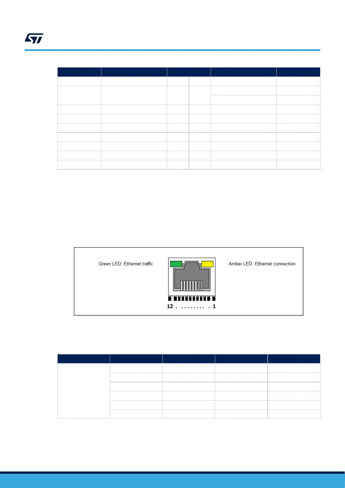
8.9 CN3 Ethernet RJ45 connector
The STM32H735G-DK board supports 10Mbps/100Mbps Ethernet communications with the U9 MICROCHIP
LAN8742A-CZ-TR PHY, and the CN3 integrated RJ45 connector. The Ethernet PHY is connected to the
STM32H735IGK6 microcontroller through an RMII interface.
The PHY 25 MHz clock is generated from the X1 oscillator, while the STM32H735IGK6 50 MHz clock is
generated by the PHY RMII_REF_CLK.
Figure 18. CN3 Ethernet RJ45 connector
The related pinout for the Ethernet connector is listed inTable 20.
Table 20. CN3 Ethernet connector pinout
Connector
Pin number Description Pin number Description
CN3
1 TX+ 7 NC
2 TX- 8 NC
3 RX+ 9 Cathode yellow LED
4 NC 10 Anode yellow LED
5 NC 11 Cathode green LED
6 RX- 12 Anode green LED
UM2679
CN3 Ethernet RJ45 connector
UM2679 - Rev 1
page 26/42

 Loading...


