– 99 –
APPENDIX
No. 1
DIP-SW1
2 3 4 5 6 7 8
No. 1
DIP-SW2
2 3 4
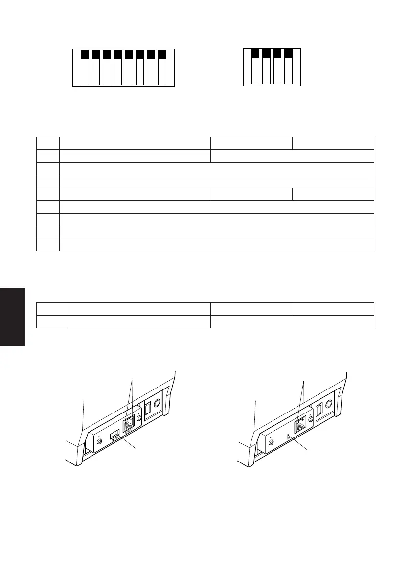
B-4. Ethernet Interface Model
ON ON
OFF OFF
Switch
Function ON OFF
1-1 Command emulation (Ster Line mode) Always ON
1-2 Should not be changed (Should be set to on)
1-3 Should not be changed (Should be set to on)
1-4 Sensor adjustment Invalid Valid
1-5 Should not be changed (Should be set to on)
1-6 Should not be changed (Should be set to on)
1-7 Should not be changed (Should be set to on)
1-8 Should not be changed (Should be set to on)
The factory settings of DIP switch are all on.
DIP-SW 2
Switch
Function ON OFF
2-1~2-4 Always ON Should be set to on
The factory settings of DIP switch are all on.
DIP-SW1
(E type) (E2 type)
LED
DIP-switch 3
 Loading...