WORKSHOP MANUAL
Map of functional units
TC 108 SD - TC 118 SD
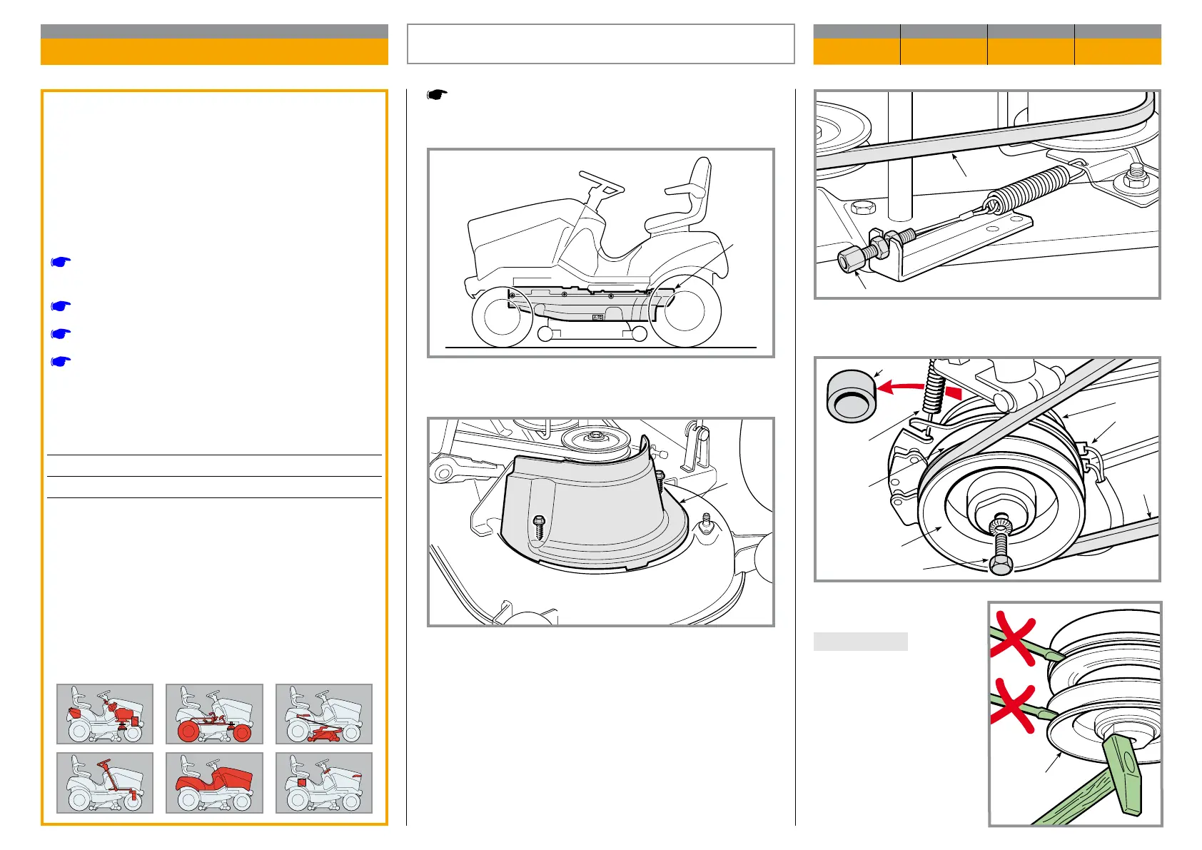
gether with the transmission control pulley (10) and
spacer (11).
IMPORTANT To remove
the clutch (9) from the en
gine shaft, absolutely do
not use a lever to force
the pulleys or the outer
cover. In case of diculty,
apply an unlocking spray
and gently tap on the hub
with a hammer, to facili
tate extraction.
Remove the front hood.
Lower the cutting deck completely.
Identify the fastening screws and remove the left ex-
ternal safety guard (1).
Also remove the left internal safety guard (2) to obtain
easier access.
Loosen and release the screw adjuster (3) to loosen
the blade control belt (4) and free it from the pulley (5).
Disconnect the connector (6), unhook the check
spring (7) from the clutch side and undo the central
screw (8); remove the clutch (9) from the shaft, to-
REMOVAL OF THE ENGINE
CHAPTER REVISION FROM ... PAGE
5.4 0 2018 1 of 2
General informations
Since there are dierent types of drive, the stag
es de scribed here refer to those shared or similar
in all types of engine.
Related topics
[
4.1] Adjusting the engagement and checking
the blade brake
[
4.3] Drive belt adjustment
[
5.1] Removal of front hood
[
6.7] Replacement of the accelerator and ad-
justment of the carburettor
Tightening torques
8 Screw for pulley ............................. 45 ÷ 50 Nm
- Screws for engine fastening ............ 25 ÷ 30 Nm

 Loading...