This service manual contains de-
tailed descriptions of all the repair
and servicing procedures specific
to this power tool series.
There are separate handbooks for
servicing procedures for stand-
ardized parts and assemblies that
are installed in several STIHL
power tool models. Reference is
made to these handbooks in the
appropriate chapters in this
manual.
As the design concept of models
FS 120, FS 200, FS 300, FS 350,
FS 400, FS 450 and FR 350, FR
450 is almost identical, the descrip-
tions and servicing procedures in
this manual generally apply to all
models. Differences are described
in detail.
You should make use of the
illustrated parts lists while carrying
out repair work. They show the
installed positions of the individual
components and assemblies.
Refer to the latest edition of the
relevant parts list to check the part
numbers of any replacement parts
needed.
Parts lists on microfiche and CD-
ROM are always more up to date
than printed lists.
A fault on the power tool may have
several causes. Consult the
troubleshooting charts for all as-
semblies in the "Standard Repairs,
Troubleshooting" handbook.
Refer to the "Technical Informa-
tion" bulletins for engineering
changes which have been intro-
duced since publication of this
service manual. Technical informa-
tion bulletins also supplement the
parts list until a revised edition is
issued.
The special servicing tools mentio-
ned in the descriptions are
listed in the last chapter of this
manual.
Use the part numbers to identify
the tools in the "STIHL Special
Tools" manual.
The manual lists all special
servicing tools currently available
from STIHL.
Symbols are included in the text
and pictures for greater clarity.
The meanings are as follows:
In the descriptions:
•
= Action to be taken as
shown in the illustration
(above the text)
- = Action to be taken that
is not shown in the
illustration
(above the text)
In the illustrations:
= Pointer
= Direction of movement
Service manuals and all technical
information bulletins describing
engineering changes are intended
exclusively for the use of STIHL
servicing dealers. They must not
be passed to third parties.
Servicing and repairs are made
considerably easier if the machine
is mounted on assembly stand (2)
5910 890 3100 with the aid of
clamp (1) 5910 890 8800.
Secure the clamp to the assembly
stand with two washers and two
M8 nuts.
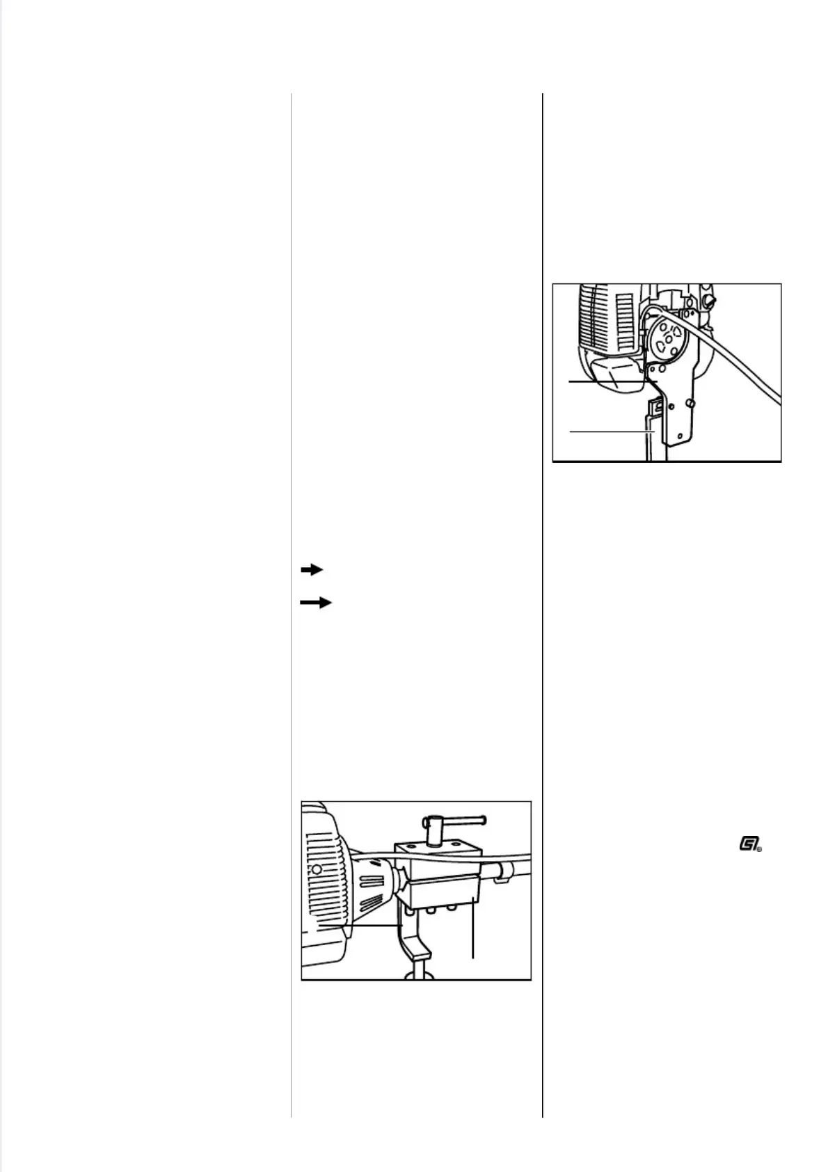
Servicing and repairs to the power-
head are considerably easier if it is
mounted on assembly stand (2)
5910 890 3100 with the aid of
clamping plate (1) 5910 890 2101.
First remove the clutch housing
and secure the powerhead to the
stand with two M6x20 and two
M10x25 hex. head screws.
The machine or powerhead can
then be swivelled to the best posi-
tion for the ongoing repair and this
leaves both hands free.
Always use original STIHL
replacement parts.
They can be identified by the
STIHL part number,
the
S T I H L
and the STIHL parts symbol
(
The symbol may appear alone on
small parts.
1. INTRODUCTION
2
5
0
R
A
2
2
8
1
2
V
A
2
5
0
R
A
2
2
7
V
A
2
1
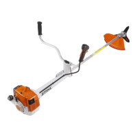
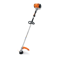
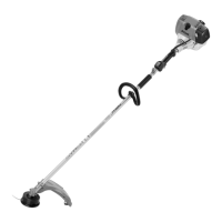
2 FS 120, 200, 300, 350, 400, 450, FR 350, 450
 Loading...