35MS 210, MS 230, MS 250
– Remove the air filter – b 11.1.
– Pull out the shutter – b 5.3.
– Pull boot off the spark plug.
The ignition lead is molded to the
module.
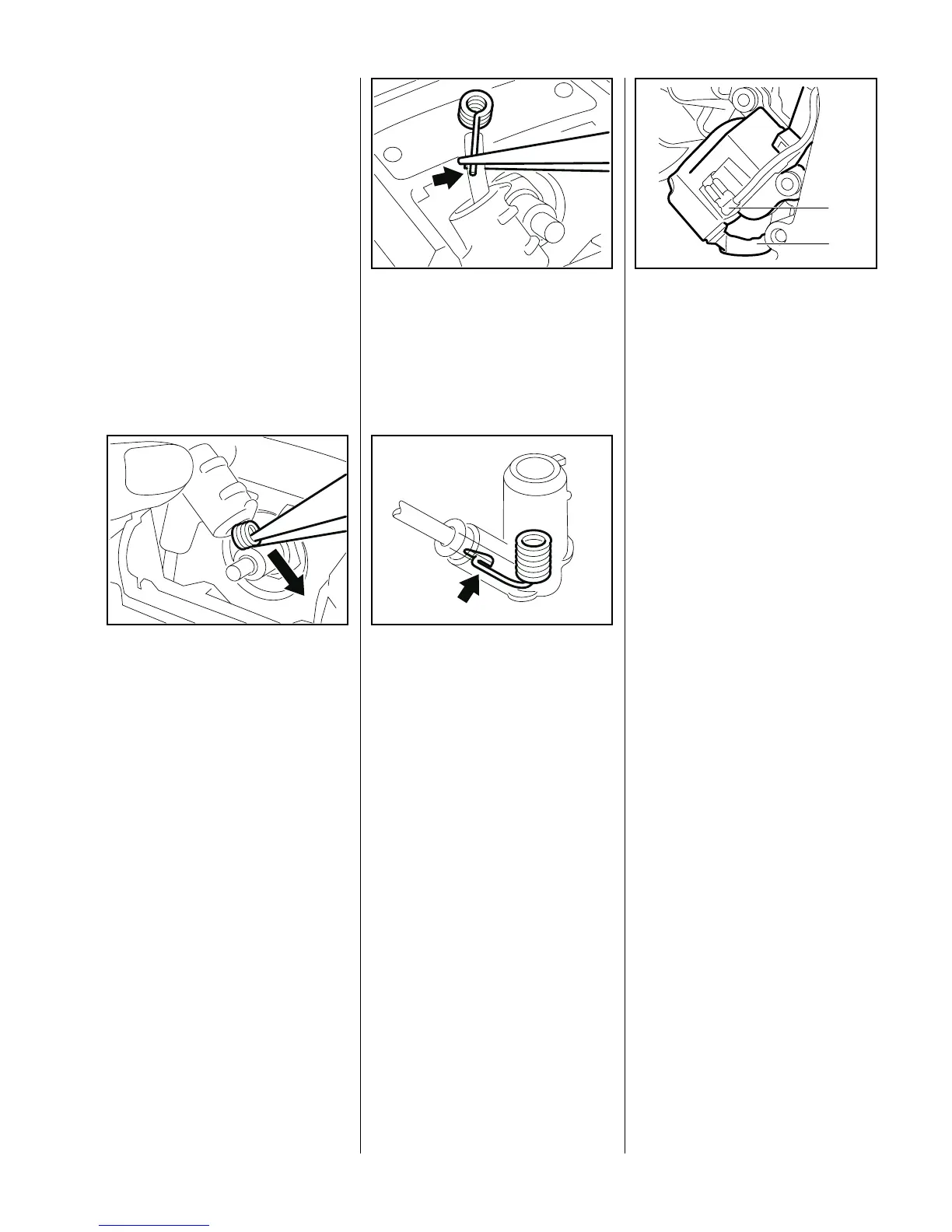
: Use pliers to grip the leg spring
and pull it out of the spark plug
boot.
– Unhook the leg spring from the
ignition lead.
– Pull the spark plug boot off the
VA
135RA107
ignition lead.
– Coat end of the ignition lead
(about 20 mm/3/4") with oil.
– Fit spark plug boot over the
ignition lead.
– Use pliers to grip the end of the
ignition lead inside the spark plug
boot and pull it out.
: Pinch the hook (arrow) of the leg
spring into the center of the lead,
i.e. about 10 mm (3/8") from the
end of the lead.
VA
135RA108
: Pull the lead back into the boot so
that the leg spring locates
properly inside it (see arrow).
If the spark plug has a separate
terminal nut, make sure that it is
properly tightened down.
VA
171RA146
– Fit boot on the spark plug.
– Fit the shutter – b 5.3.
– Install the air filter – b 11.1.
The ignition module accommodates
all the components required to
control ignition timing. There are
two electrical connections on the
coil body:
: the high voltage output with
ignition lead (1),
VA
208RA008
2
1
: the connector tag (2) for the short
circuit wire.
Accurate testing of the ignition
module is only possible with a
special tester. For this reason it is
only necessary to carry out a spark
test in the workshop.
A new ignition module must be
installed if no ignition spark is
obtained (after checking that wiring
and stop switch are in good
condition).
7.1 Spark Plug Boot 7.2 Ignition Module
 Loading...