Installation Information
Built-In
Built-In
(600-
(600-
2
2
)
)
Series
Series
2-2
#3758407 - Revision B - August, 2006
IF UNIT IS UNDER A SOLID SOFFIT AND CLEARANCE BETWEEN SOFFIT AND TOP OF UNIT IS GREATER
THEN 1” (25.4 mm), OR IF UNIT IS NOT UNDER SOLID SOFFIT, UNIT COULD TIP FORWARD UNDER CER-
TAIN LOAD CONDITIONS. FAILURE TO INSTALL ANTI-TIP COMPONENTS AND EXTEND LEVELERS TO
FLOOR ACCORDING TO INSTALLATION MANUAL COULD RESULT IN SERIOUS INJURY OR DEATH.
INSTALLATION CONSIDERATIONS
This section covers common installation issues seen by Service Technicians. Improper installation, though not a
valid service issue, has the potential to lead to a call for service. Installation related complaints could include, but
are not limited to: Unit leveling, unit movement, door misalignment, improper door and drawer sealing, internal frost
or condensation, exterior condensation, warm compartment temperatures, etc.
NOTE: If additional installation information is needed, refer to the complete Installation Guide, or contact Sub-Zero
Service Department.
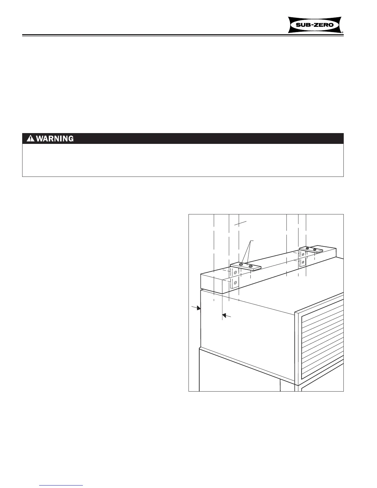
Anti-Tip Components Installation (All Models)
If anti-tip components (aka wood block / blocking kit)
need be installed, follow these steps:
NOTE: These directions are supplied with each anti-tip
package.
1. Locate and mark two wall studs at back of unit
installation location (See Figure 2-1).
2. Identify and mark proper height to clear unit top.
Space between unit top and bottom of wood block
must NOT be more then 1/4" (6.1 mm) (See Figure
2-1).
3. Using the L-brackets and screws provided, secure
wood block to wall studs, located in step 1, making
sure screws extend 7/8" (22.2 mm) into each wall
stud. The wood block must extend a minimum of 3"
(76.2 mm) over unit (See Figure 2-1).
4. Utilizing front and rear levelers, raise and level unit
until it contacts wood block.
5. Refer to Installation Guide provided with the unit for
any additional information needed.
 Loading...