Built-In
Built-In
(600-
(600-
2
2
)
)
Series
Series
Electronic Control System
3-3
#3758407 - Revision B - August, 2006
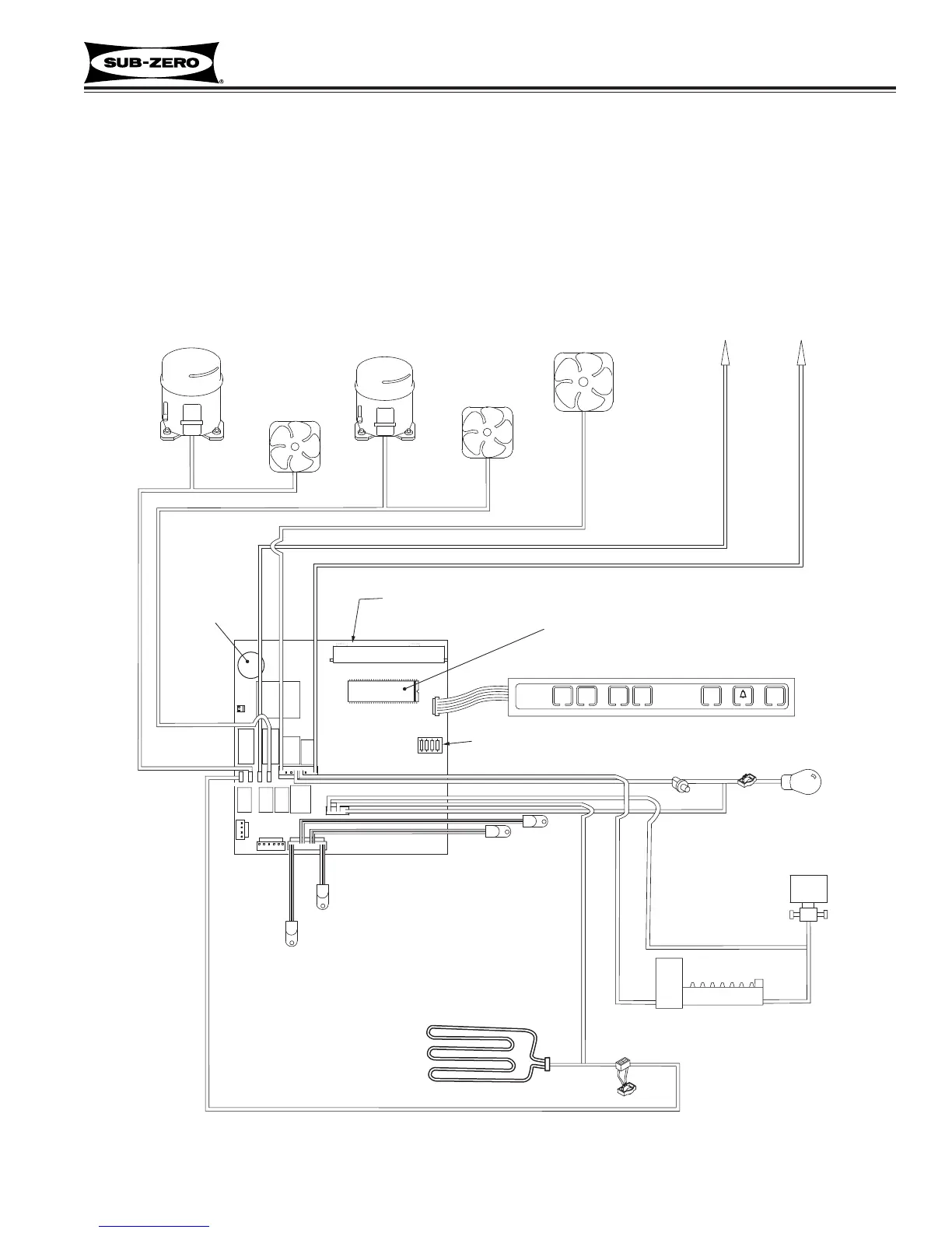
Figure 3-1. Basic 600-2 Series Electronic Control System Diagram
BASIC 600-2 SERIES ELECTRONIC CONTROL SYSTEM
This page contains a basic illustration of the 600-2 Series electronic control system (See Figure 3-1). Input opera-
tions for the electronic control system are performed at the membrane switch (part of the the control panel assem-
bly), with monitoring, regulating and controlling functions taking place at the control board (located directly behind
the control panel). Temperatures and possible problems with the unit are displayed at the control panel on the LCD.
The entire electronic control system is described in greater detail on the following pages.
NOTE: The diagram below is not an exact electrical representation of the electronic control system. For more detailed
electrical diagrams refer to the wiring diagram and schematic supplied with the unit.
SOL. MONITOR LINE
 Loading...