Built-In
Built-In
(600-
(600-
2
2
)
)
Series
Series
Installation Information
2-3
#3758407 - Revision B - August, 2006
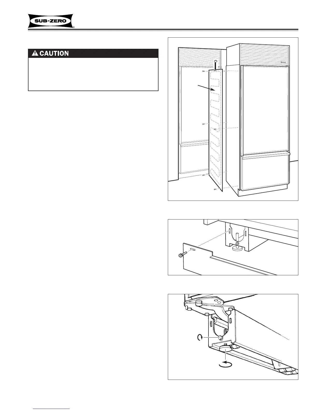
Figure 2-4. Unit Leveling
Figure 2-3. Kickplate Removal
Unit Leveling (All Models)
NOTE: Unit must be installed before final leveling. If
unit is anchored to cabinets, remove anchor screws
before leveling, reinstalled after.
1. To level unit, first remove kickplate (See Figure 2-3).
2. To raise unit front, turn front leveler legs counter-
clockwise, clockwise to lower (See Figure 2-4).
3. At front of unit base is an adjusting screw that reach-
es to rear leveler/roller assembly. To raise unit rear,
use 5/16” socket wrench to turn adjusting screw
clockwise to raise, counterclockwise to lower (See
Figure 2-4).
NOTE: Level is best checked at top & side mainframe.
Kickplate
Turn adjusting
screws
clockwise
to raise rear
Turn front levelers
counterclockwise
to raise front.
Unit Base
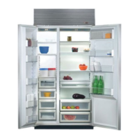
Dual Unit Installations
Apply
heater
to left
side of
unit that
is to
right of
other
unit.
If two or more units are placed side by side and are
2” or less apart, a dual unit heater package should
be applied to the left side of the right hand unit.
Failure to install the dual unit heater package could
result in exterior condensation between the units.
• Sales Accessory part #TTDUAL should be utilized.
(See Figure 2-2)
NOTE: Complete installation instructions are sup-
plied with the #TTDUAL package.
Figure 2-2. Dual Unit Heater
 Loading...