2} INSTALLATION
Assembling the kit components
• Attach the rod end ® and nut © onto the steering damper ®
B
Tightening torque: 10 - 16 N°m (1.0 - 1.6 kg-m)
• Mount the bracket ©over the steering damper®, attach bolt ©together with lock washer® and screw
the bolt to bring it to finger tight.
• Attach the bolt © together with lock washer ® onto the bracket ® and bring the bolt to finger tight.
• Connect the rod end ®to the bracket® using bolt (4), lock washer ®, spacer ®and nut ®as shown in
the illustration. Tighten the nut ® to specification.
Tightening torque: 4
—
7 N®m (0.4 - 0.7 kg-m)
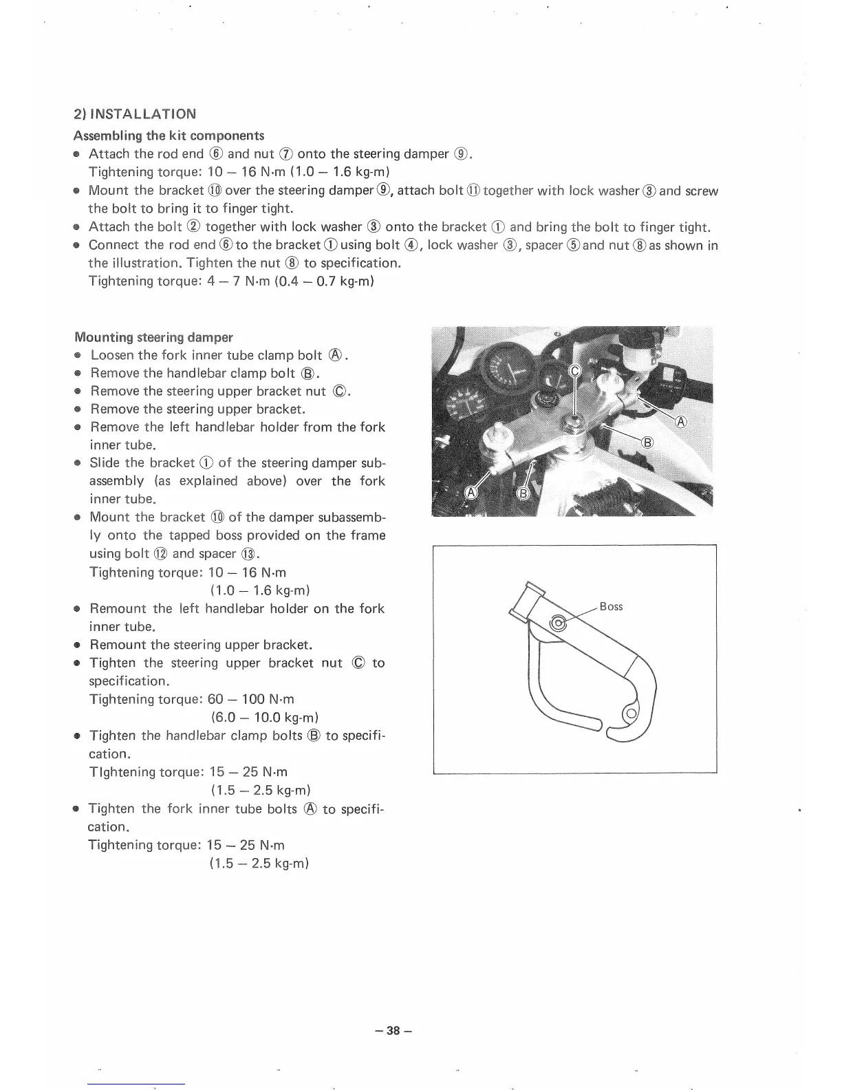
Mounting steering damper
® Loosen the fork inner tube clamp bolt ®.
• Remove the handlebar clamp bolt (§).
• Remove the steering upper bracket nut ®-
• Remove the steering upper bracket.
• Remove the left handlebar holder from the fork
inner tube
8
• Slide the bracket ® of the steering damper sub-
assembly (as explained above) over the fork
inner tube.
• Mount the bracket © of the damper subassemb-
ly onto the tapped boss provided on the frame
using bolt © and spacer (Q).
Tightening torque: 10
—
16 N-m
(1.0-1.6 kg-m)
• Remount the left handlebar holder on the fork
inner tube.
• Remount the steering upper bracket.
• Tighten the steering upper bracket nut © to
specification.
Tightening torque: 60—100 N-m
(6.0-
10.0 kg-m)
• Tighten the handlebar clamp bolts ® to specifi-
cation.
Tightening torque: 15
—
25 N-m
(1.5 -2.5 kg-m)
• Tighten the fork inner tube bolts ® to specifi-
cation.
Tightening torque: 15
—
25 N-m
(1.5-2.5 kg-m)
-38-
 Loading...