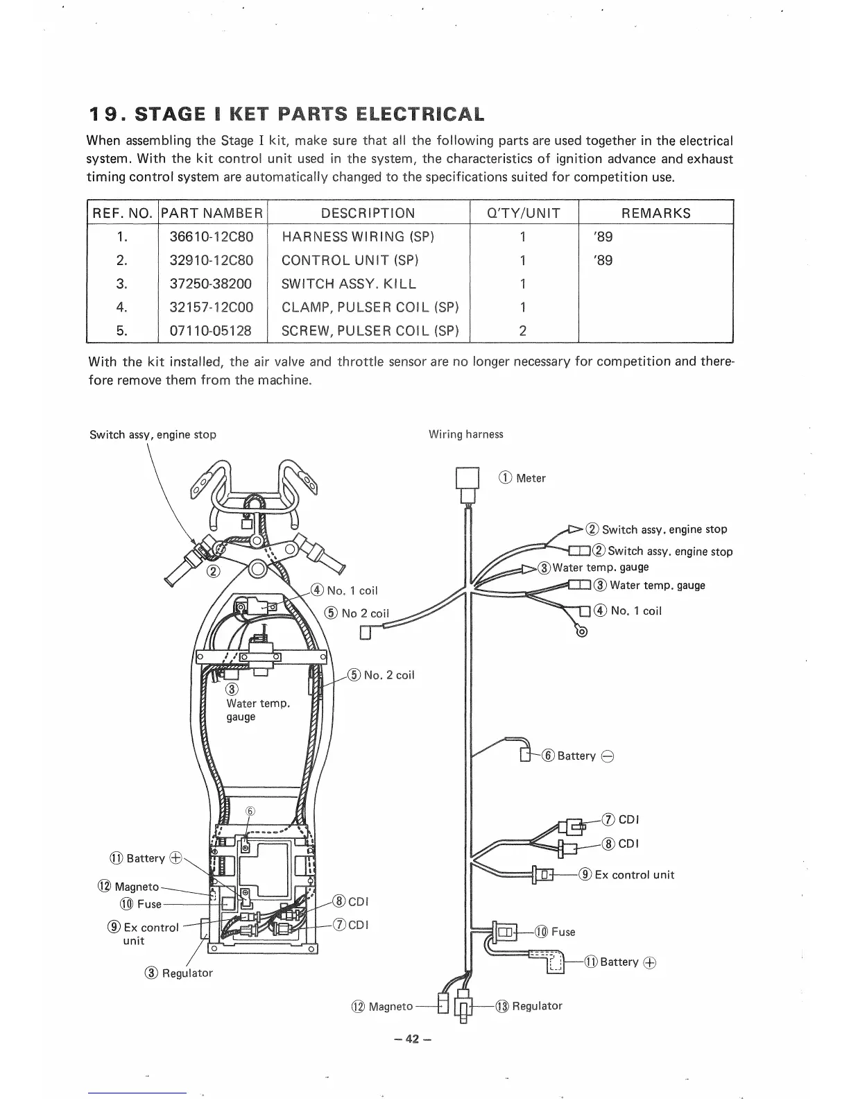
1 9. STAGE I KET PARTS ELECTRICAL
When assembling the Stage I kit, make sure that all the following parts are used together in the electrical
system.
With the kit control unit used in the system, the characteristics of ignition advance and exhaust
timing control system are automatically changed to the specifications suited for competition use.
IREF. NO.
1.
2.
3.
4.
5.
PARTNAMBER
36610-12C80
32910-12C80
37250-38200
32157-12C00
07110-05128
DESCRIPTION
HARNESS WIRING (SP)
CONTROL UNIT (SP)
SWITCH ASSY. KILL
CLAMP, PULSER COiL(SP)
SCREW, PULSER COIL (SP)
QTY/UNIT
1
1
1
1
2
REMARKS
'89
'89
With the kit installed, the air valve and throttle sensor are no longer necessary for competition and there-
fore remove them from the machine.
Switch assy, engine stop
Wiring harness
■®
No. 1 coil
©No 2 coil
(Q) Battery ©
J) Magneto
@Fuse
© Ex control
unit
® No. 2 coil
(D Regulator
PI ® Meter
^*C>(2) Switch assy, engine stop
Switch assy, engine stop
(D Water temp, gauge
(3) Water temp, gauge
® No, 1 coil
k^k
© Battery ©
Dl——(9) Ex control unit
Battery ©
Regulator