31
Inserttheedgesoftheguardintheframeprofileinthegroovethatisintheframeprofile,andconnect
bothpartsoftheguardatthemiddlewith2screws.
Replacethevibrationdampingfoamrubberlistifitisdamaged.
i.3.Installation‐electrical
i.3.1Description
Thepositionofcomponentsisshownanddescribedinannex2.
Connectionstoterminalsareshowninthewiringdiagram–annex16.
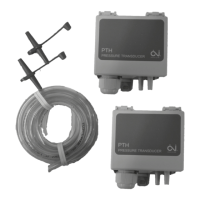
Whencontrolofconstantpressureintheducts(alsocalleddemandcontrolledcapacity)isrequired,the
pressuretransmittersmustmeasureintheductsystematplaceswhereall
pressurechangescanbe
registeredaccuratelyforreliablepressurecontrol.Thisplacementislefttothecustomer’sfreechoice.
Itisimportanttoachieveaconstantpressure–alsoforthemostfarawaydiffusers.
i.3.2Wiringdiagrams
Thewiringdiagramsareprintedinseparatemanualsdelivered withtheunitsasannex16.
Thewiringdiagramsarenotuniquefortheorderspecificunits,butitisstandardwiringdiagramswithdata
aboutallconfigurationsoftheunits.Herebythewiringdiagramswillinformaboutcomponentsthatarenot
orderedanddelivered.Seetheorderconfirmationandannex2withexactinformationabouttheaccessory
componentsthatareorderedanddelivered.
Thewiringdiagramincludes:
Generaldescription,Circuitdiagrams,Cabinetlayout,TerminalmatrixandCableplan.
ThewiringdiagramsareontheDVDdeliveredwitheveryunit.
i.3.2.1TIME
units‐labelsonthecabinetnexttothesupplyfan
Labelwithdataaboutthecabinet–includingdataaboutfuses–seesectiond.2.2
Flowchart–seesectiond.2.3–standardandnotuniquefortheorderspecificunit
Labelwithterminalplanforexternalcomponents–
seesectiond.2.5–standard,andnotuniquefor
theorderspecificunit
i.3.2.2DVunits–labelsonorwiththecabinet
Labelwithdataaboutthecabinet–includingdataaboutfuses–seesectiond.2.2
Flowchart–seesectiond.2.3–uniquefortheorder
specificunit–printedwiththeunique
productionnumberoftheunit
Labelwithterminalplanforexternalcomponents–seesectiond.2.5–standard,andnotuniquefor
theorderspecificunit
i.3.3Installationofmainspowersupply
AnAC/DCresidualcurrentdevicemustbeinstalledinthepowersupply.Thepowersupplyfortheunitsis
3*400V+N+PE‐50Hz.Protectionoftheunitsinaccordancewiththelocalstatutoryrequirementsforthe
additionalprotectionofsystemswithfrequencyconverters.
i.3.3.1Necessarymainspower
supplyforTIMEunitswithecmotorsandwithoutDVU
Necessarymainspowersupplyinthetablebelowandinthewiringdiagraminannex16.Thisinformationis
alsoprintedontheuniquemachinecardplacedonthefrontofeveryunit(seeexampleofamachinecard
in
sectiond.2.1).
 Loading...