8.15.2
T2000-A70 Data Modem Kit
M2000-00
31/12/97 Copyright TEL
8.15.1 Components Required
The T2000-A70 kit contains the following components:
8.15.2 Fitting
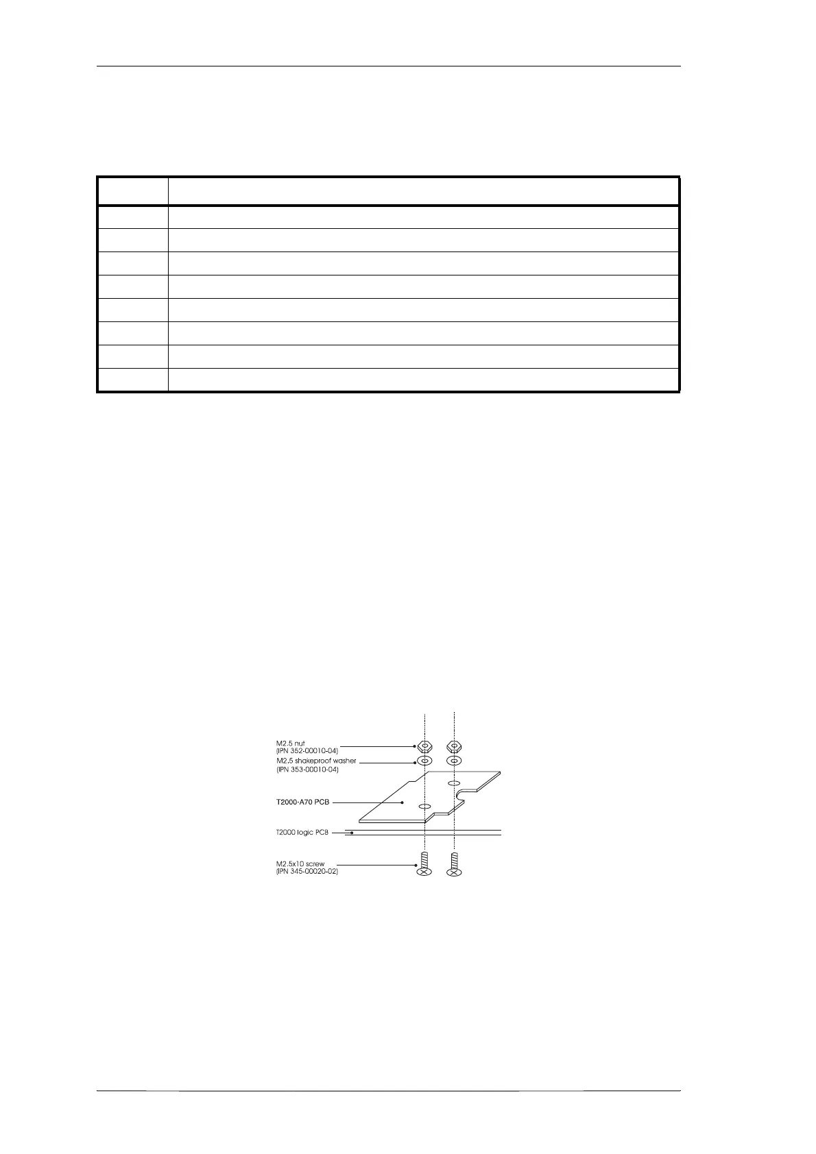
Refer to Figure 8.15.2.
1 Remove the top cover of the radio by unscrewing the 4 bottom cover screws,
unscrew the logic PCB and fold out.
2 T2000-A70 Mounting
Position the data modem PCB on the top side of the logic PCB, as shown, match-
ing P3 on the bottom side of the data modem PCB to connector S3 on the logic
PCB.
Use the 2 M2.5x10mm screws, nuts and shakeproof washers to secure in place, as
shown.
Figure 8.15.1 T2000-A70 PCB Mounting
The screws are fitted from the bottom of the logic PCB, and secured with the nuts
and washers on the top side of the data modem PCB.
Torque the screws to 2.5in.lb.
Caution:
Over-tightening the screws will cause damage to the data modem PCB,
and compression of connector P3.
* Discard unused parts from the female screw lock kit.
Quantity Description
1 T2000-A70 data modem PCB assembly
1 Data interface decoupling PCB assembly (refer to Section 7.17)
1 connecting loom
2 M2.5x10mm pan Pozi Taptite screws
2 M2.5 shakeproof washer
2M2.5 nut
1 female screw lock kit (in plastic bag)
*
24-40x
5/16
pan Pozi Taptite screws (black)
 Loading...