8.16.4
T2000-A03/-A04/-A16 Remote Loom Kits
M2000-00
31/12/97 Copyright TEL
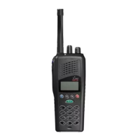
Figure 8.16.2 Connector PCB Mounting
5 T2000 Series II Chassis
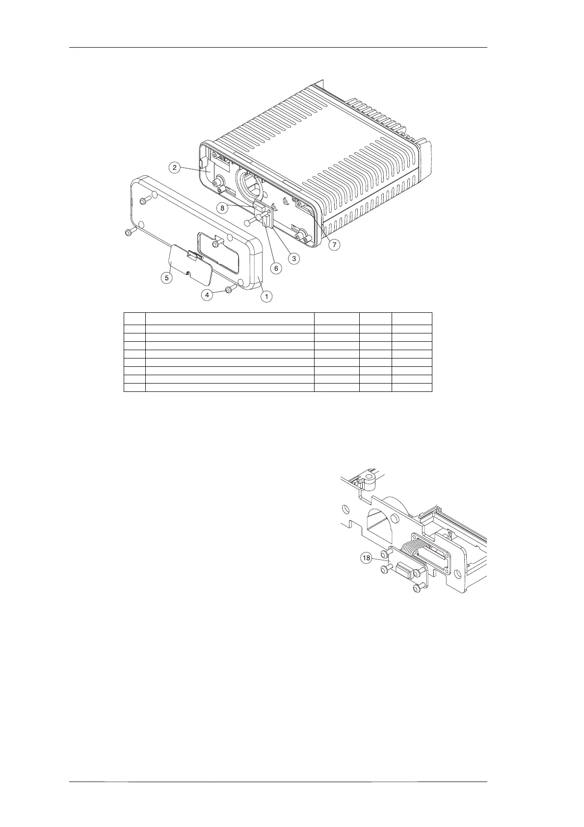
Refer to Figures 8.16.3 and 8.16.4.
Fit the EMC filter PCB (18) provided in the kit to
the chassis, first passing the loom on the bottom
side of the PCB through the chassis hole, as
shown.
Secure the EMC filter PCB in place, using the 4
M3x8 Taptite screws.
Note:
EMC model radios will already have an EMC
filter PCB fitted. Check that the top side con-
nector (SKT-1) is 8 way. If not, discard the exist-
ing filter PCB and fit the new PCB provided.
Figure 8.16.3 EMC FIlter PCB Mounting
Plug the EMC filter PCB loom onto the logic PCB.
Unclip the remoting connector cover (5) from the dummy front panel (1), and pass
the unconnected end of the remote loom through the holes in the dummy front
panel and the adaptor plate (2).
Plug the 8 way loom connector onto the 8 way connector (6) on the top side of the
EMC filter PCB.
T2000-A16 kit: Secure the remote loom drain wire solder tag under one of the
EMC filter PCB screws.
Item Description IPN Quantity Torque (in.lb)
1 DUMMY FRONT PANEL 316-06433-XX 1
2 ADAPTOR PLATE (T2000 SERIES I) 301-00001-XX 1
3 CONNECTOR PCB 220-01274-XX 1
4 NO 4X3/8 SCREW (DUMMY FRONT PANEL SCREWS) 349-00010-22 4 8 (0.9Nm)
5 REMOTING CONNECTOR COVER 316-85125-XX 1
6 8 WAY CONNECTOR PCB SOCKET (FOR REMOTE LOOM) 240-04020-50 1
7 SLOTS IN ADAPTOR PLATE & CHASSIS FOR LOGIC PCB LOOM
8 8 WAY CONNECTOR PCB SOCKET (FOR LOOM TO LOGIC PCB) 240-04020-50 1
 Loading...