EasyManua.ls Logo

Tait T2000 II Series User Manual

Tait T2000 II Series
150 pages
To Next Page IconTo Next Page
To Previous Page IconTo Previous Page
Page #131 background imageLoading...
Page #131 background image
M2000-00
T2000-A70 Data Modem Kit
8.15.7
Copyright TEL 31/12/97
Message Format
All message packets take the general form:
[IDENT][SIZE][PARAMETERS][CHECKSUM]<CR>
The following table explains each component of the message packet.
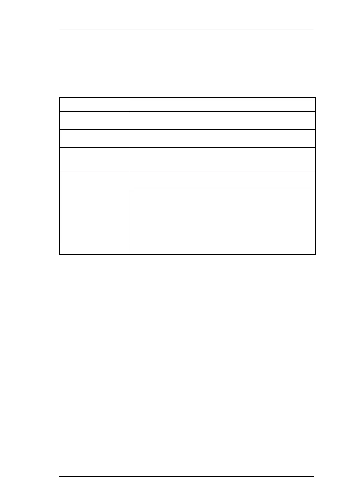
Table 8.15.1 Message Format
General message format characteristics:
All fields in a message are encoded in ASCII, except for the [PARAMETERS] field of
the transmit and receive commands, which is encoded in Binary.
Where numeric values are represented in ASCII-hex notation (two characters per
byte), digits A to F are upper case.
The minimum length of a command packet is 5 characters (i.e. this is when [SIZE] =
00).
The maximum length of the [PARAMETERS] field is 111 characters. The maximum
length of the command packet is therefore 116 characters ([SIZE] = 0x6F).
Message Component Description
[IDENT]
The message identifier. Identifiers are single ASCII characters (lower-case
alphabetical) which categorise the message type.
[SIZE]
The number of characters which make up the
[PARAMETERS
] field.
[SIZE]
is an 8-bit number expressed in ASCII-hex notation (two characters).
[PARAMETERS]
An optional field, depending upon the command. Parameter values are
generally character strings, unless explicitly stated otherwise. Parameter
type is dependent upon the command - there is no explicit type definition.
[CHECKSUM]
An 8 bit checksum of fields
[IDENT]
,
[SIZE]
and
[PARAMETERS]
. It is
expressed in ASCII-hex notation (two characters).
Calculating
[CHECKSUM]
:
[CHECKSUM]
is calculated by applying the following algorithm:
1
Take the modulo-2 sum of all message bytes preceding
[CHECKSUM].
2
Retain bits 0 to 7, discarding any higher order bits resulting from the
summation.
3
Form the two’s complement of the remainder.
4
Convert the binary number into two ASCII-hex digits, MSD first.
<CR>
The packet terminator. It is the ASCII “carriage return” character ($0D).

Table of Contents

Question and Answer IconNeed help?

Do you have a question about the Tait T2000 II Series and is the answer not in the manual?

Tait T2000 II Series Specifications

General IconGeneral
Channel Spacing12.5/20/25 kHz
Operating Temperature-30°C to +60°C
Frequency Range136-174 MHz
Power OutputVHF: 1-5W, UHF: 1-4W
Dimensions130 x 57 x 37 mm (with standard battery)
GPSOptional

Summary

Introduction

About This Manual

Scope

Defines the manual's coverage of T2000 Series II mobile two-way radios.

Format

Manual is in a ring binder for adding revision packages.

Revision Control

Explains how page updates are marked and identified.

PCB Information

Information provided for all current and previous issue PCBs.

Technical Information

Errors

Instructions on how to report errors or suggestions for improvement.

Ordering Tait Service Manuals

How to order service manuals from Tait branches or dealers.

1 General Information

1.2 Specifications

Detailed performance specifications for T2000 Series II radios.

1.3 Operating Instructions

Guidance on operating the T2000 Series II radios.

2 Circuit Description

2.1 Design Overview

Provides a general overview of the circuit design.

2.4 TCXO/TX Audio PCB

Information on the TCXO/TX Audio Printed Circuit Board.

2.6 T2000-100 & -400 RF PCB

Details the RF PCB for T2000-100 and T2000-400 models.

3 Introduction To Servicing

3.1 Servicing Precautions

Essential precautions to observe during servicing procedures.

3.2 Disassembly Instructions

Step-by-step guide for disassembling radio components.

3.3 Power Amplifier - Special Instructions

Special procedures for Power Amplifier components.

4 Functional Tests

4.1 Test Equipment Required

Lists the necessary equipment for functional testing.

4.4 Receiver Performance Tests

Procedures for testing receiver performance parameters.

4.5 Transmitter Performance Tests

Procedures for testing transmitter performance parameters.

5 Fault Finding

5.5 Receiver RF Checks

Specific RF checks for receiver troubleshooting.

5.6 Transmitter RF Checks

Specific RF checks for transmitter troubleshooting.

5.10 Fault Finding Charts

Provides charts to help diagnose common faults.

6 Tuning & Adjustment

6.1 Tuning Precautions

Essential precautions before performing tuning and adjustment.

6.2 Tuning & Adjustment Points

Identifies tuning and adjustment points on RF and TCXO/Tx audio PCBs.

6.4 Transmitter Adjustments

Procedures for adjusting transmitter parameters.

6.5 Receiver Adjustments

Procedures for receiver alignment and adjustment.

7 PCB Information

7.1 T2000-100 RF PCB

Parts list, diagrams, and component locations for T2000-100 RF PCB.

7.6 T2000-700/-900 RF PCB

Parts list, diagrams, and component locations for T2000-700/-900 RF PCB.

7.9 T2000 TCXO/Tx Audio PCB

Parts list, diagrams, and component locations for T2000 TCXO/Tx Audio PCB.

7.10 T2010 & T2015 HC05 Logic PCB

Parts list, diagrams, and component locations for T2010/T2015 HC05 Logic PCB.

7.11 T2020, T203X, T2040, T2050 & T2060 HC11 Logic PCB

Parts list, diagrams, and component locations for T2020/T203X/T2040/T2050/T2060 HC11 Logic PCB.

8 Accessories

8.1 T2008 Power Supply

Information on the T2008 Power Supply accessory.

8.10 T2000-A450X CTCSS & Scrambler Kits

Details on T2000-A450X CTCSS and Scrambler kits.

8.13 T2000-A66 Single Port UART Kit

Information on the T2000-A66 Single Port UART Kit.

8.15 T2000-A70 Data Modem Kit

Information on the T2000-A70 Data Modem Kit.

8.16 T2000-A03/-A04/-A16 Remote Loom Kits

Information on remote loom kits for T2000 radios.

9 Software

9.1 Identifying The Software Version Number

How to identify the software version number on T2000 radios.

Related product manuals