3.10
Introduction To Servicing
M2000-00
30/12/97 Copyright TEL
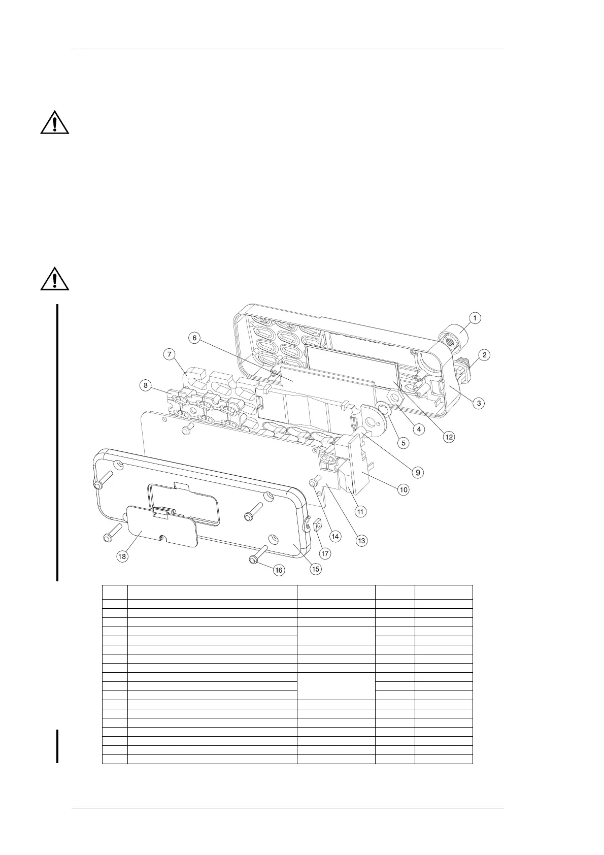
With the control head face down, gently remove the PCB (13), along with the key-
pad (8) and lightspreader (7).
Do not disturb the positioning or height of the LEDs, as this is critical for reas-
sembly.
Carefully remove the LCD (6) and lens (12).
Lay the front panel (3) on a horizontal surface, with the light spreader (7) in place.
Remove the volume knob (1) and volume knob nut (5) to access the lightspreader
and keypad (8).
Before reassembly, the LCD and PCB edge connectors should be wiped with alco-
hol.
Take care to ensure the alcohol does not come in contact with the coating on the
light spreader, as this will dissolve on contact with alcohol.
Figure 3.6 T2020, T2040 & T2050 Control Head Assembly - Remotely Mounted
Item Description IPN Quantity Torque (in.lb)
1KNOB 1
2 MICROPHONE GROMMET 360-02003-XX 1
3 FRONT PANEL 316-06427-XX 1
4 VOLUME POT NUT
SEE PARTS LIST
(SECTION 7)
1
5 VOLUME POT WASHER 1
6 LIQUID CRYSTAL DISPLAY (LCD) 008-02029-XX 1
7 LIGHTSPREADER 304-07036-XX 1
8 ENHANCED KEYPAD 311-03096-XX 1
9 VOLUME POT
SEE PARTS LIST
(SECTION 7)
1
10 POT PCB 1
11 MICROPHONE CONNECTOR 1
12 LENS 312-01046-XX 1
13 CONTROL HEAD PCB (T2020, T2040 OR T2050) SEE SECTION 7 PARTS 1
14 NO 4X3/8 SCREW (CONTROL HEAD SCREWS) 349-00010-22 3 8
15 REMOTE BACK PANEL 318-08432-XX 1
16 NO 4X5/8 SCREW (REMOTE BACK SCREWS) 349-00010-24 4 8
17 CAPTIVE NUT M4 PRESSED 352-00010-17 2
18 REMOTING CONNECTOR COVER 316-85125-XX 1
 Loading...