32
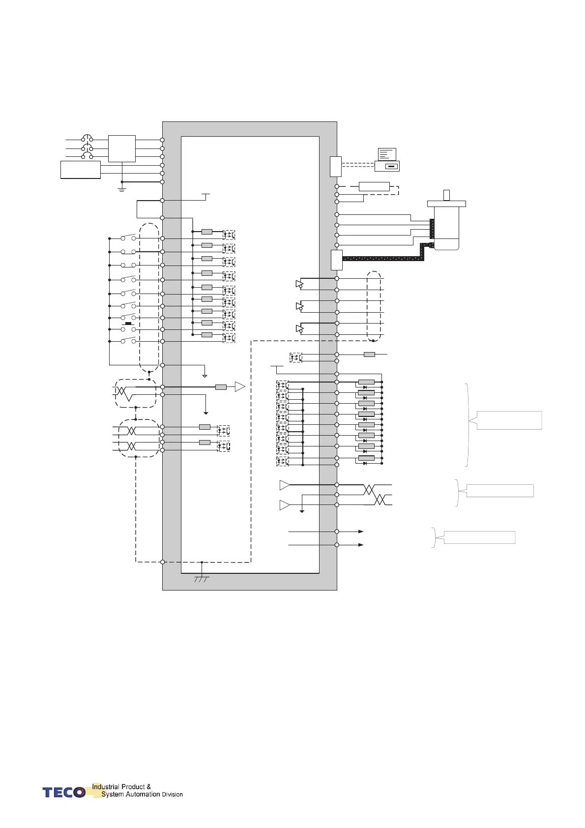
2-3 Typical Circuit Wiring Examples
2-3-1 Position Control Mode (Pe Mode) (Line Driver)
U
NFB
1
R1
R1
R1
R1
R1
R1
R1
R1
R1
4
5
9
3
6
12
2
7
48
IG24
TIC
AG
FG
C
N
4
PC
RS232
PC
P1
P
Regeneration resistor
V
W
FG
Encoder
SERVO
MOTOR
C
N
2
35
36
37
38
39
40
43
44
Z0
DOCOM
*2
R4
+Vc
External supply
18
19
20
21
22
23
24
25
DC24V
45
44
LOAD
LOAD
LOAD
LOAD
LOAD
LOAD
LOAD
LOAD
DOCOM
*2
30
31
32
MON1
AG
MON2
Analog Monitor Output 1
Analog Signal Grounding
Analog Monitor Output 2
33
34
+15V
-15V
+15V PW output (AG)
50
Vc=24V, R4=4.7KΩ
SERVO
R2
27
29
20K
Ω
Pulse/CW/A Phase (+)
14
15
16
17
R3
R3
330Ω
330
Ω
DC 24V
R
S
T
s, 0V
Supply
Filter
R
S
T
FG
47
45
DI-1
DI-4
DI-5
DI-9
DI-3
DI-6
DI-12
DI-2
DI-7
DO-1
DO-2
DO-3
DO-4
DO-5
DO-6
DO-7
DO-8
Encoder Output A Phase
PA
/PA
PB
/PB
PZ
/PZ
Servo ON
(SON)
CCW Limit ( CCWL)
CW Limit
(CWL)
Emergency stop
(EMC)
PI/P Switch
(PCNT)
External Torque Limit
(TLMT)
Mode control
(MDC)
Alarm clear
(ALRS)
Pulse error clear (CLR)
Torque Limit
Analog Signal Grounding
Servo in limit/ Alarm Code 2
Servo Ready
(RDY)
Alam(ALM)
Zero Speed (ZS)
Positioning
Completed(INP)
Limiting Torque/Alarm Code 0
P in Action/Alarm Code 1
Base Block /Alarm Code 3
+24V
ground
Max Voltage 24V
Max Output Current 10mA
Pulse
/Pulse
Sign
/Sign
IP24
DICOM
Internal +24V DC
Digital input common
Shielded wire
Grounding
’
Pulse/CW/A Phase (-)
Sign/CCW/B Phase (+)
Sign/CCW/B Phase (
-)
Encoder Output /A Phase
Encoder Output B Phase
Encoder Output /B Phase
Encoder Output /Z Phase
Encoder Output Z Phase
Vc=12V, R4=2.4KΩ
Vc=5V, R4=1.0KΩ
Max Output Current 5mA
-15V PW output (AG)
Max Output Current 10mA
r, 24V
Control Power
Supply
Notes: 1. Pe mode =External pulse positioning command
2. DOCOM means common port of digital input
(DOCOM must connect to IG24 when using internal power supply)
 Loading...