has been connected to the power line with the
power-line filter plug (P420) disconnected
from the battery charger, C417 and C418 will
remain charged until P420 is connected to the
charger or discharged
by
the grounding method.
E3
Some
of
the circuit boards in this instrument
are multi-layer type boards with conductive ·
paths laminated between the top and
bottom
board layers.
All
soldering on these boards
should
be
done with extreme care to prevent
breaking the interconnections between the
layers. Only experienced maintenance per-
sonnel should
attempt
repair
of
these boards.
The-reliability
and
accuracy
of
this
instrument
can
be
main-
tained
only
if
proper
soldering
techniques
are
used
when
re-
pairing
or
replacing
parts.
General
soldering
techniques
that
A1
ATTENUATOR
BOARD
A3
AID
CONVERTER
BOARD
HOLD-DOWN
NUTS*
A6
SECONDARY
POWER SUPPLY
BOARD
(INSIDE
COVER)
A4
AMPLIFIER
BOARD
Maintenance-213
Service
apply
to
maintenance
of
any
precision
electronic
equipment
should
be used
when
working
on
this
instrument.
Ordinary
60/40
rosin-core
electronic-grade
solder
and
a
15-watt
solder-
ing iron
is
adequate
for
most
soldering
in
the
213.
Should
a larger
wattage
soldering
iron
be
required
on
some
of
the
metal
shields
or
larger
common
connection
circuit
pads,
use
a
35-watt
or
40-watt
pencil-type
soldering
iron.
After
soldering
is
completed,
clean
the
area
around
the
solder
connection
with
isopropyl
or
ethyl
alcohol.
Be careful
not
to
remove
any
information
printed
in
the
area.
Component Removal and Replacement
Since
component
removal
and
replacement
requires
instru-
ment
disassembly,
replacement
procedures
for
the
batteries,
crt,
and
circuit
boards
will
be
explained
first.
These
replace-
ment
procedures
are
written
so
that
in
most
cases, each pre-
ceding
component
must
be
removed
before
the
following
component
is
removed
(e.g.
the
batteries
must
be
removed
before
the
A/0
Converter
Board
is
removed).
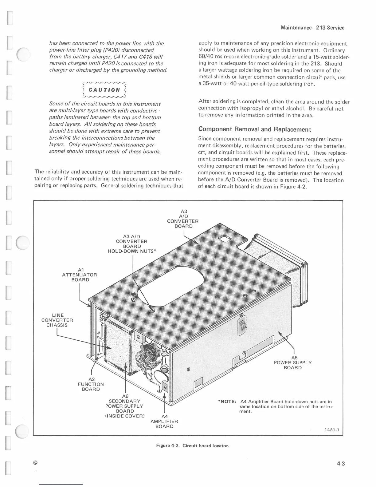
The
location
of
each
circuit
board
is
shown
in
Figure
4-2.
*NOTE:
A4
Amplifier
Board
hold-down
nuts
are in
same
location
on
bottom
side
of
the
instru-
ment.
1481-1
Figure
4-2.
Circuit board locator.
@
4-3
 Loading...


