Cal
ibration-213
Service
d. Set
the
Standard
output
to
+1.000
V.
e.
CHECK-Reading
of +1.000 ±
0.025
(0.975
to
1.025).
f.
Disconnect
the
Standard.
12. CHECK RMS
VOLTAGE
MEASUREMENT
ACCURACY
NOTE
The
AC
Calibration Standard
is
required
to
verify
the specified accuracy
of
each rms
voltage range
with
this procedure (step 12).
See
footnote
3
in
Table 6-1.
If
an
AC
Cali-
bration
Standard is
not
available, the
follow-
ing procedures are
provided
as
alternatives to
the
procedure
following
this note.
(a)
If
all
previous calibration steps have been
accomplished, each
circuit
function
involved
in rms voltage measurement has been checked
and
adjusted; therefore,
further
rms voltage
measurement accuracy checks
may
not
be
necessary
for
the instruments
intended
use.
(b) The procedure
and
equipment
used
in
Calibration
step 10 can also be used
to
verify
the
0.
1,
1,
10,
and
100 V rms
ranges.
The
1000 V range can
be
checked,
but
the
output
of
the Sinewave Generator
is
not
sufficient
to
provide
the
minimum
10%
of
full
scale
input
to
verify
the performance specification.
(c) Calibration step 12A
is
an alternate
method
of
verifying the
0.
1,
1,
10,
and
100 V
rms
ranges_
The 1000 V range also can be
checked
with
this alternate procedure,
but
the rms value
of
the 100 V
fixed
output
of
the
Amplitude
Calibrator
is
not
sufficient
(at least
10%
of
full
scale) to
verify
the per-
formance specification.
a. Set INPUT COUPLING
to
AC.
b. Connect
the
probe
to
the
AC
Calibration Standard
(Voltage configuration) with a dual banana-plug
to
BNC
adapter and a probe adapter.
c.
Set VOL
TS-mA/DIV
and
the
Standard
as
show
in
Table 6-9.
6-16
d.
CHECK-Reading
is
within limits shown in Table 6-9.
e.
Disconnect
the
Standard.
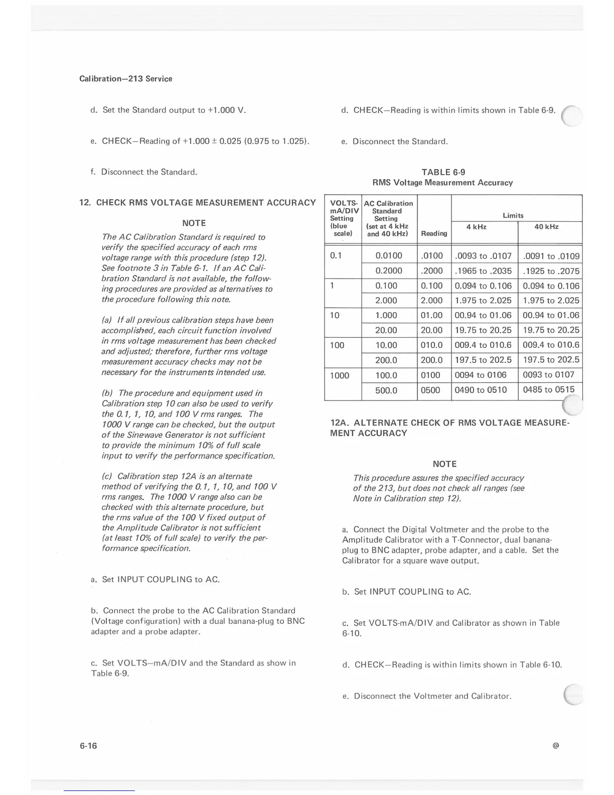
TABLE 6-9
RMS Voltage Measurement Accuracy
VOLTS-
AC
Calibration
mA/DIV
Standard
Limits
Setting
Setting
(blue
(set
at
4
kHz
4
kHz
40
kHz
scale)
and
40
kHz)
Reading
0.1
0.0100
.0100
.0093
to
.0107
.0091
to
.0109
0.2000
.2000
.1965
to
.2035
.1925
to
.2075
1
0.100
0.100
0.094
to
0.106
0.094
to
0.106
2.000 2.000
1.975
to
2.025
1.975
to
2.025
10
1.000
01.00
00.94
to
01.06
00.94
to
01.06
20.00
20.00
19.
75
to
20.25
19. 75
to
20.25
100
10.00
010.0
009.4
to
010.6
009.4
to
010.6
200.0
200.0
197.5
to
202.5
197 .5
to
202.5
1000
100.0
0100
0094
to
0106
0093
to
0107
500.0
0500
0490
to
0510
0485
to
0515
12A.
ALTERNATE
CHECK OF RMS
VOLTAGE
MEASURE-
MENT
ACCURACY
NOTE
This procedure assures the specified accuracy
of
the 213,
but
does
not
check
all
ranges
(see
Note
in
Calibration step 12).
a.
Connect
the
Digital
Voltmeter
and the
probe
to
the
Amplitude Calibrator with a T-Connector, dual banana-
plug
to
BNC
adapter, probe adapter, and a cable. Set
the
Calibrator for a square wave
output.
b. Set INPUT COUPLING
to
AC.
c.
Set VOL TS-mA/DIV and Calibrator
as
shown
in
Table
6-10.
d.
CHECK-Reading
is
within limits shown
in
Table 6-10.
e.
Disconnect
the
Voltmeter and Calibrator.
@
 Loading...


