b.
Connect
the
Resistance Standard
to
the
mA-n
and
common
jacks using
two
banana plug
to
BNC
adapters
and a cable.
Set
the
Standard
to
20
kn.
c.
CHECK-Reading
is20.00±0.11
(19.89to20.11).
d.
ADJUST-Ohms
Adj, R215, for a reading of 20.00.
9.
CHECK
RESISTANCE
MEASUREMENT
ACCURACY
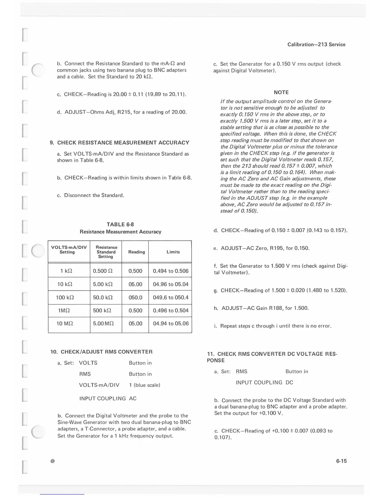
a.
Set
VOL TS-mA/DIV and
the
Resistance Standard
as
shown
in
Table 6-8.
b.
CHECK-Reading
is
within limits shown
in
Table 6-8.
c. Disconnect
the
Standard.
TABLE
6-8
Resistance Measurement Accuracy
VOL TS-mAIDIV
Resistance
Setting
Standard
Reading Limits
Setting
1
kn
o.5oo
n
0.500
0.494
to
0.506
10
kn
5.00
kn
05.00
04.96
to
05.04
100
kn
50.0
kn
050.0
049.6
to
050.4
1Mn
500
kn
0.500
0.496
to
0.504
10
Mn
5.00
Mn
05.00
04.94
to
05.06
10.
CHECK/ADJUST
RMS
CONVERTER
@
a.
Set: VOL TS
RMS
VOL TS-mA/DIV
Button ·
in
Button
in
1 (blue scale)
INPUT COUPLING
AC
b.
Connect
the
Digital
Voltmeter
and
the
probe
to
the
Sine-Wave
Generator
with
two
dual banana-plug
to
BNC
adapters, a T-Connector, a probe
adapter,
and a cable.
Set
the
Generator
for
a 1 kHz frequency
output.
Cal
ibration-213
Service
c.
Set
the
Generator for a
0.150
V rms
output
(check
against Digital Voltmeter).
NOTE
If
the
output
amplitude control on the Genera-
tor is
not
sensitive enough to be adjusted to
exactly 0.150 V rms
in
the above step, or to
exactly 1.500 V rms is a later step, set
it
to a
stable setting that
is
as
close
as
possible to the
specified voltage. When this
is
done, the CHECK
step reading
must
be
modified to that shown on
the Digital Voltmeter plus or minus the tolerance
given in the CHECK step
(e.g.
if
the generator
is
set such that the Digital Voltmeter reads
0.
151,
then the
213
should read 0.157 ± 0.007, which
is
a limit reading
of
0.150 to
0.
164).
When mak-
ing the
AC
Zero and
AC
Gain
adjustments, these
must
be
made to the exact reading on the
Digi-
tal Voltmeter r3ther than to the reading speci-
fied in the
ADJUST
step
(e.g.
in
the example
above,
AC
Zero would be adjusted to
0.
157
in-
stead
of
0.150).
d.
CHECK-Reading
of
0.150
± 0.007 (0.143
to
0.157).
e.
ADJUST-AC
Zero, R195, for
0.150.
f.
Set
the
Generator
to
1.500
V rms (check against
Digi-
tal
Voltmeter).
g.
CHECK-Reading
of
1.500
±
0.020
( 1.480
to
1.520).
h.
ADJUST
-AC
Gain R 188, for 1.500.
i.
Repeat steps c through i until
there
is
no
error.
11.
CHECK
RMS
CONVERTER
DC
VOLTAGE
RES-
PONSE
a.
Set:
RMS
Button
in
INPUT COUPLING
DC
b.
Connect
the
probe
to
the
DC
Voltage
Standard
with ·
a dual banana-plug
to
BNC
adapter and a
probe
adapter.
Set
the
output
for
+0.100
V.
c.
CHECK-Reading
of
+0.100
± 0.007
(0.093
to
0.107).
6-15
 Loading...


