Maintenance-213
Service
Disassembly.
The
probe
can
be
disassembled
by
referring
to
the
Exploded
View
drawing
in
the
Mechanical
Parts
List
section
and
the
following
disassembly
instructions:
1.
The
test
prod
tip
is
retained
by
a
tight
fit
only,
and
is
removed
and
reinstalled
by
pulling it
off
or
pushing it
on
the
probe
body
assembly.
2.
The
probe
body
assembly
is
removed
by
pulling it
out
of
the
cable
assembly
probe
head,
and reinstalled
by
push-
ing it
onto
the
same
probe
head.
3.
The
common
clip lead
is
removed
from
and
reinstalled
on
the
probe
head
by
pulling it
out
of
or
pushing
it
into
the
slot
in
the
probe
head.
COAXIAL-TYPE
END
LEAD
CONNECTOR REPLACE-
MENT.
Replacement
of
the
coaxialtype
end
lead
connec-
tor,
such
as used
on
the
probe
lead and its
corresponding
instrument
lead,
requires
special
tools
and
techniques.
It
is
recommended
that
the
complete
lead
assembly
be re-
placed,
or
that
replacement
be
referred
to
the
local
Tek-
tronix
Field
Office
or
representative.
LED ASSEMBLY REPLACEMENT.
Replacement
instruc-
tions
for
the
LED
Assembly
are
included
in
the
Side
Panel
Removal
and
Replacement
instructions.
INTERCONNECTING
CABLE
AND
TERMINAL
CONNEC-
TOR
REPLACEMENT.
The
interconnecting
cable
assem-
blies are
factory
' assembled
items,
and
consist
of
machine
installed
end-lead
connectors
mounted
in
plastic
holders
to
make
up
multi-connector
plugs.
The
plastic
holders
are easi-
ly
replaced
as individual
items,
but
if
the
cables are
faulty,
it
is
recommended
that
these
be
replaced as a
complete
as-
sembly.
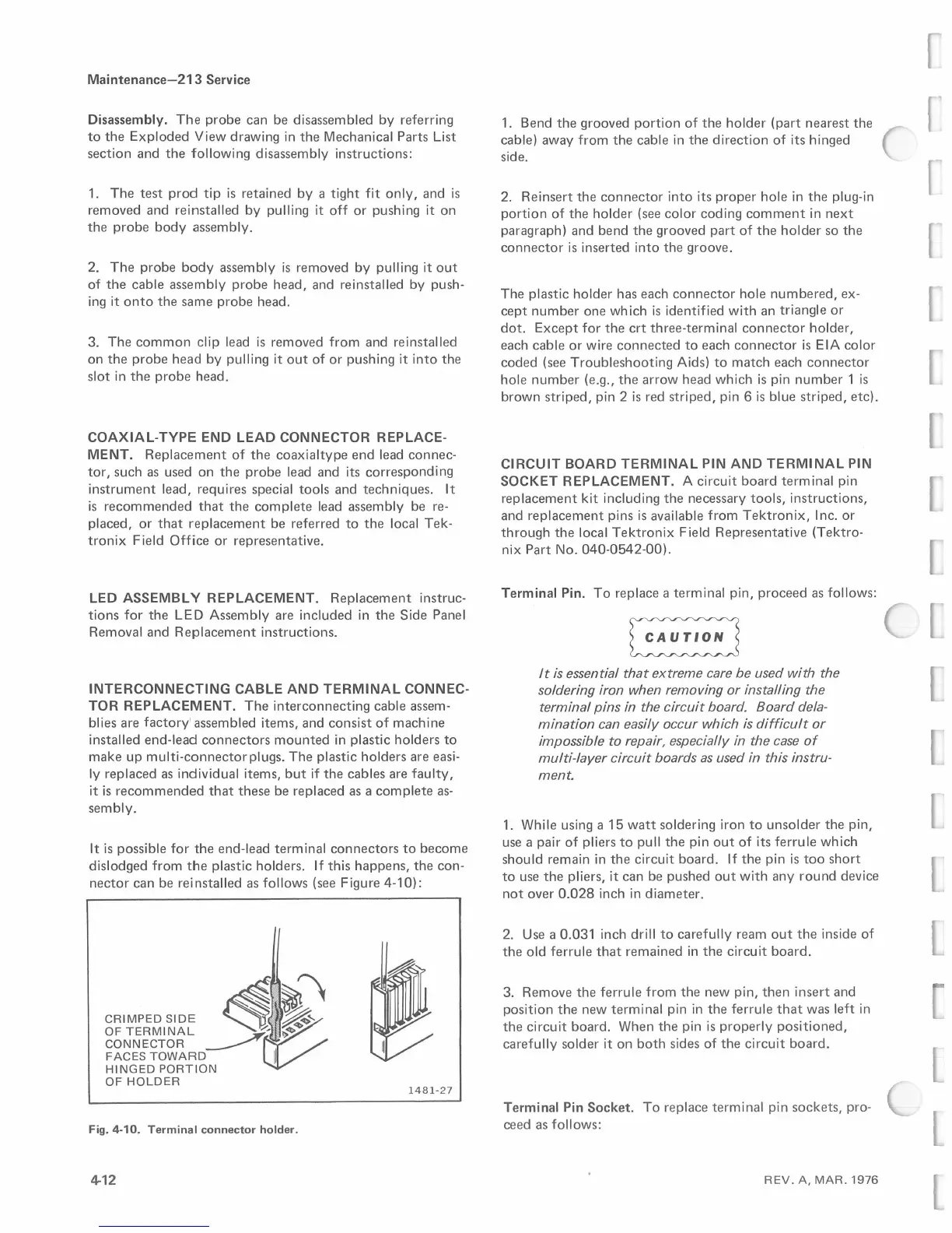
It
is
possible
for
the
end-lead
terminal
connectors
to
become
dislodged
from
the
plastic
holders. If
this
happens,
the
con-
nector
can
be
reinstalled
as follows (see
Figure
4-10):
~,
CRIMPED
SIDE
~~'
OF
TERMINAL
~
;
~-<c>
CONNECTOR
_.--
I
FACES
TOWARD
I
HINGED
PORTION
OF
HOLDER
1481-27
Fig. 4-10. Terminal connector holder.
4-12
1. Bend
the
grooved
portion
of
the
holder
(part
nearest
the
cable)
away
from
the
cable
in
the
direction
of
its
hinged
side.
2.
Reinsert
the
connector
into
its
proper
hole
in
the
plug-in
portion
of
the
holder
(see
color
coding
comment
in
next
paragraph)
and
bend
the
grooved
part
of
the
holder
so
the
connector
is
inserted
into
the
groove.
The
plastic
holder
has
each
connector
hole
numbered,
ex-
cept
number
one
which
is
identified
with
an
triangle
or
dot.
Except
for
the
crt
three-terminal
connector
holder,
each
cable
or
wire
connected
to
each
connector
is
EIA
color
coded
(see
Troubleshooting
Aids)
to
match
each
connector
hole
number
(e.g.,
the
arrow
head
which
is
pin
number
1
is
brown
striped,
pin 2
is
red
striped,
pin 6
is
blue
striped,
etc).
CIRCUIT
BOARD
TERMINAL
PIN
AND
TERMINAL
PIN
SOCKET REPLACEMENT. A
circuit
board
terminal
pin
replacement
kit including
the
necessary
tools,
instructions,
and
replacement
pins
is
available
from
Tektronix,
Inc.
or
through
the
local
Tektronix
Field
Representative
(Tektro-
nix
Part
No.
040-0542-00).
Terminal
Pin.
To
replace a
terminal
pin,
proceed
as follows:
~
It
is
essential that extreme care
be
used with the
soldering iron when removing or installing the
terminal pins
in
the circuit board. Board dela-
mination can easily occur which
is
difficult or
impossible to repair, especially
in
the case
of
multi-layer circuit boards
as
used
in
this instru-
ment.
1. While using a
15
watt
soldering iron
to
unsolder
the
pin,
use a
pair
of
pliers
to
pull
the
pin
out
of
its
ferrule
which
should
remain
in
the
circuit
board.
If
the
pin
is
too
short
to
use
the
pliers,
it
can
be
pushed
out
with
any
round
device
not
over
0.028
inch
in
diameter.
2. Use a
0.031
inch drill
to
carefully
ream
out
the
inside
of
the
old
ferrule
that
remained
in
the
circuit
board.
3.
Remove
the
ferrule
from
the
new
pin,
then
insert
and
position
the
new
terminal
pin
in
the
ferrule
that
was
left
in
the
circuit
board.
When
the
pin
is
properly
positioned,
carefully
solder
it
on
both
sides
of
the
circuit
board.
Terminal
Pin
Socket.
To
replace
terminal
pin
sockets,
pro-
ceed
as follows:
REV.
A,
MAR.
1976
 Loading...


