Maint_
enance-213
Service
TABLE
4-1
NOTE
(cont.)
Power Supply Operating Tolerances
Power
Test
Supply
Point
+6.5V
TP550
-6.5V
TP555
+15 V
TP545
+75 V
TP540
-1000V
TP530
DIPPED
TANTALUM
ELECTROL
YTICS:
+
LEAD
LEAD
CERAMIC
CAPACITORS:
4-16
Output Voltage
Tolerance
±6.4 ± 0.3 V
±0.3V
± 0.15 V
±3V
±
10
V
COLOR
SILVER
GOLD
BLACK
BROWN
RED
ORANGE
YELLOW
GREEN
BLUE
VIOLET
GRAY
WHITE
(NONE)
Typical Ripple
(Peak to Peak)
5mV
5mV
5mV
0.1
V
Do
not
measure
Whenever the instrument is connected to the
power line during internal troubleshooting,
it
should
be
connected through a line isolation
transformer. This protects the operator from
a possible shock hazard from the instrument
floating power-line system, and protects the
instrument from damage should the test in-
strument earth ground
be
connected to the
213
power line connection.
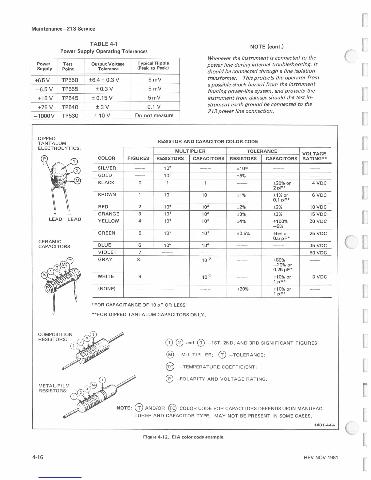
RESISTOR
AND
CAPACITOR
COLOR
CODE
MULTIPLIER
TOLERANCE
VOLTAGE
FIGURES
RESISTORS
CAPACITORS
RESISTORS
CAPACITORS
RATING**
---
10
2
---
±10%
---
---
---
101
---
±5%
---
---
0 1
1
---
±20%
or
4 voe
2
pF*
1
10
10
±1%
±1%
or
6 voe
0.1
pF*
2
10
2
10
2
±2% ±2%
10VDC
3
10
3
10
3
±3% ±3%
15
voe
4
10
4
10
4
±4%
+100%
20VDC
-9%
5
10
5
10
5
±0.5% ±5%
or
25
voe
0.5
pF*
6
106
10
6
---
---
35
voe
7
---
---
---
---
50VDC
8
---
10-2
---
+80%
---
-20%
or
0.25
pF*
9
---
10·1
---
±10%
or
3 voe
1
pF*
---
---
---
±20%
±10%
or
---
1
pF*
*FOR
CAPACITANCE
OF
10
pF
OR LESS.
**FOR
DIPPED
TANTALUM
CAPACITORS
ONLY.
G)
0 and ®
-1ST,
2ND,
AND
3RD
SIGNIFICANT
FIGURES:
@
-MULTIPLIER;
G)
-
TOLERANCE:
@
-TEMPERA
T
URE
COEFFICIENT;
0 -
POLARI
TY
AND
VOLTAGE
RATING.
NOTE:
0
AND/OR
@
COLOR
CODE
FOR
CAPACITORS
DEPENDS
UPON
MANUFAC-
TURER
AND
CAPACITOR
TYPE.
MAY
NOT
BE
PRESENT
IN
SOME
CASES.
1481-44A
Figure 4-12.
EIA
color
code
example.
REV NOV
1981
 Loading...


