Section 2- 2215A
Op
erators
PREPARATION FOR USE
FIRST-TIME START
UP
SAFETY
Refer
to
the "Operators Safety Summary"
at
the front
of
this
manual
for
power
source,
grounding,
and
other
safety
considerations pertaining
to
the use
of
the 2215A. Before
connecting the instrument
to
a power source, carefully read
the following about line voltages, power cords, and fuses.
LINE VOLTAGE
The instrument is capable
of
continuous operation using
input voltages that range from
90
V
to
250 V nominal
at
frequencies from 48 Hz
to
440
Hz.
POWER CORD
A detachable three-wire power cord with a three-contact
plug is provided with each instrument
to
permit connection
to both the power source and protective grou
nd.
The plug
protective-ground contact connects (through the protective-
ground conductor)
to
the accessible metal parts
of
the in-
strument. For electrical-shock protection, insert this plug
only into a power outlet that has a securely grounded pro-
tective-ground contact.
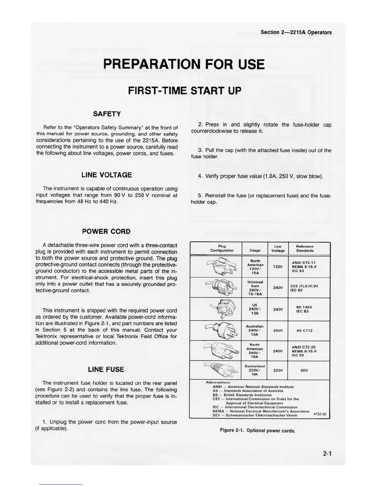
This instrument is shipped with the required power cord
as
ordered by the customer. Available power-cord informa-
tion are illustrated in Figure 2
-1
, and part numbers are list
ed
in Section 5
at
the back
of
this manual. Contact your
Tektronix representative or local Tektronix Field Office for
additional power-cord information.
LINE FUSE
The instrument fuse holder is located on the rear panel
(see Figure 2-2) and contains the line fuse. The following
procedure can be used
to
verify that the proper fuse is in-
stalled
or
to
install a replacement fuse.
1. Unplug the power cord from the power-input source
(if applicabl
e).
2. Press in and
sl
ightly rotate the fuse-holder cap
counterclockwi
se
to
release it.
3. Pull
th
e cap (with the attached fuse inside) out
of
the
fuse holder.
4. Verify proper fuse value (1.0A,
25
0 V, slow blow).
5.
Reinstall the fuse (or replacement fuse) and the fuse-
holder cap.
Plug
l
ine
Reference
Configuration
Usage
Vo
l
tage
Standards
Nonh
ANSI
C73
.11
Ame
r
ican
120V
NEMA 5.
15
.p
1
20V
/
IEC
83
15A
Universal
Euro
240V
CEE
(7I.
11
.IV
,
VII
24
0V
/
IEC83
10-16A
UK
BS
1363
24
0V
/
24
0V
IEC
83
13A
Austra
l
ian
24
0V
/
24
0V
AS
C1
12
10A
N
orth
ANSI
C73
.
20
American
240V
/
240V
NE
MA 6•
15
-P
.
1
5A
IEC
83
Swit:ierland
220V
/
220V
SEV
10A
Abbreviations:
ANSI
-
American
Nationa
l
Standards
Institute
AS
-
Standards
Association
of
Australia
BS
- British
Standards
Inst
itution
CEE
-
International
Commission
on
Rules
for
the
Approval
of
Electrical
Equipmen
t
IEC
-
International
Electro
technical
Commission
NEMA
-
National
Electrical M anufacturer
·s
As
sociation
4732-
02
SEV
Schweizevischer
Ele
ktr
otechischer
Verein
Fig
ur
e 2-1. Optional power
co
rds.
2-1

 Loading...


