Preparation for Use- 2215A Operators
CONTROLS, CONNECTORS, AND INDICATORS
The following descriptions are intend
ed
to
familiarize the
operator with the location, operation, and function
of
the
instrumen
t's
controls, connectors, and indicators.
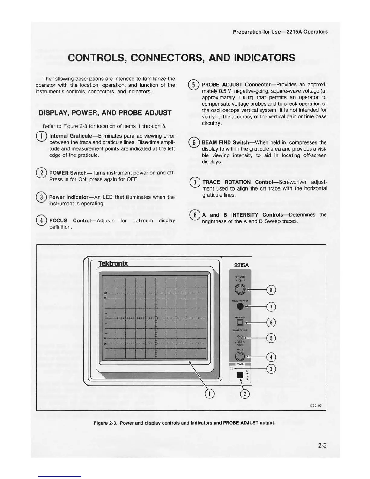
DISPLAY, POWER, AND PROBE ADJUST
Refer
to
Figure 2-3 for location
of
items 1 through
8.
1
Inte
rn
al Graticule-Eliminates parallax viewing error
between the trace and graticule lines. Rise-time ampli-
tude and measurement points are indicated at the left
edge
of
the graticule.
2 POWER Switch- Turns instrument power on and off.
Press in for
ON
; press again for OFF.
3 Power Indicato
r-An
LED that illuminates when the
instrument is operating.
4 F
OC
US Control
-Adjus
ts for optimum display
definition.
Tektronix
I
...
I
....
....
..
.. .
..
. ..
..
....
..
....
.
..
. .
..
....
..
..
....
·
..
.',
'
....
....
5
PROBE
ADJUST
Connector-
Prov
id
es
an
approxi-
mately 0.5 V, n
eg
ative-going, square-wave voltage (at
approximately 1 kH
z)
that permits
an
operator
to
compensate voltage probes and
to
check operation
of
the oscilloscope vertical system. It is not intended for
ve
rifying the accuracy
of
the vertical gain
or
ti
me-base
circuitry.
6 BEAM
FIND
Switch
-When
held in, compresses the
display to within the graticule area and provides a visi-
ble viewing int
en
sity
to
aid
in
locating off-screen
displays.
7
TRACE ROTATION
Control-
Screwdriver adjust-
ment used to
al
ign the crt trace with the horizontal
graticule lines.
8 A and B INTENSITY Controls
-De
termines the
br
ightness
of
the A and B Sweep traces.
2215A
::-:
l
. ...
. ,
..
•
--
.... .
...
\
4732-
03
Figure 2-3. Po
wer
and display controls and indicators and PROBE ADJUST output.
2-3

 Loading...


