Operating
Pro
ce
dur
es-
2215A Ope
ra
tors
Pu
lse Jitter Time Measurement
To
measure pulse jitter time:
1. Perform steps 1 through 7
of
the preceding "Magni-
fied
Sweep Runs After Delay· procedure.
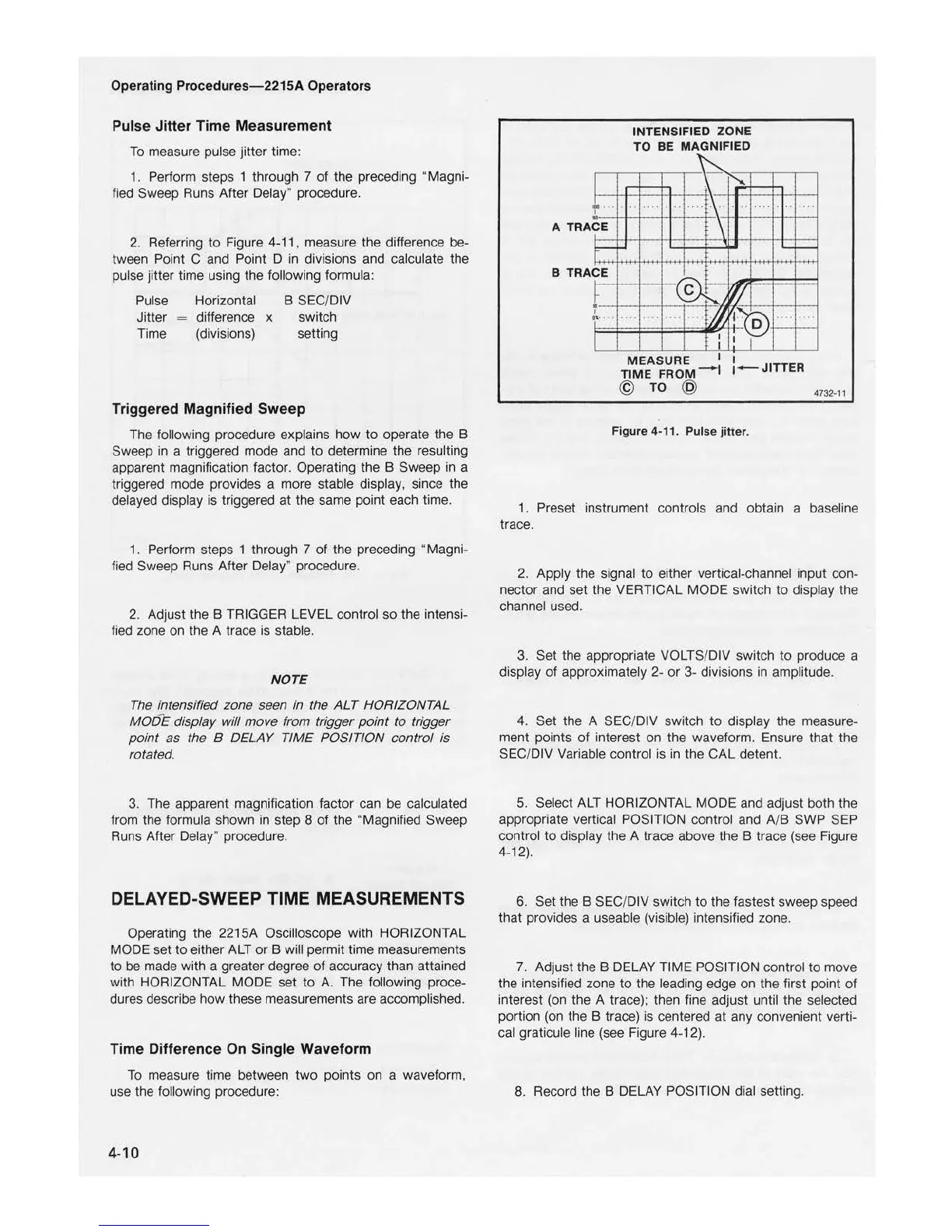
2. Referring
to
Figure 4-11 , measure the difference be-
tween Point C and Point D
in
divisions and calculate the
pulse jitter time using the following formula:
Pulse Horizontal B SEC/DIV
Jitter difference x
sw
itch
Time (divisions) setting
Triggered Magnified Sweep
The following procedure explains
how
to
operate the B
Sweep
in
a triggered mode and
to
determine the resulting
apparent magnification factor. Operating the B Sweep
in
a
triggered mode provides a more stable display, since the
delayed display is triggered at the same poi
nt
each time.
1. Perform steps 1 through
7
of
the preceding "Magni-
fied
Sweep Runs After Delay" procedure.
2. Adjust the B TRIGGER LEVEL control
so
the intensi-
fied zone on the A trace is stable.
NOTE
The
intensified zone seen in the
ALT
HORIZONTAL
MODE
display will move from trigger
point
to
trigger
point
as the B DELAY TIME POSITION control
is
rotated.
3. The apparent magnification factor can be calculated
from the formula shown
in
step 8
of
the "Magnified Sweep
Runs After Delay· procedure.
DELAYED-SWEEP TIME MEASUREMENTS
Operating the 2215A Oscilloscope with HORIZONTAL
MODE set
to
either ALT
or
B will permit time measurements
to
be made with a greater degree
of
accuracy than attained
with HORIZONTAL MODE set to
A.
The following proce-
dures describe how these measurements are accomplished.
Time Di
ffe
ren
ce
On Single Waveform
To
measure time between
two
points on a waveform,
use the following procedure:
4-10
I
!.
....
I.
A TRAC E
r
B TRAC E
r
I
t \
··
I
I
INTENSIFIED ZONE
TO BE MAG
NI
FIED
........
~
~
. ,
,,,
.
.
..
.
·
·\
\
~
~I
'II
.
...
.... ....
M
~
I
I
I
I
--
. ... ..
,,
MEASURE
I
I
TI
ME
FROM-I
i-
JIT
TER
@
TO
@
4732·11
Figure 4-11. Pulse jitter.
1 . Preset instrument controls and obtain a baseline
trace.
2. Apply the signal
to
either vertical-channel input con-
nector and set the VERTICAL MODE switch
to
display the
channel used.
3. Set the appropriate VOLTS/DIV switch
to
produce a
display
of
approximately 2-
or
3-
divisions in amplitude.
4. Set the A SEC/DIV switch
to
display the measure-
ment points
of
interest on the waveform. Ensure that the
SEC
/DIV Variable control is in the CAL detent.
5. Select ALT HORIZONTAL MODE and adjust both the
appropriate vertical POSITION control and A/B SWP
SEP
control to display the A trace above the B trace (see Figure
4-12).
6.
Set the B SEC/DIV switch to the fastest sweep speed
that provides a useable (visible) intensified zone.
7. Adjust the 8 DELAY TIME POSITION control
to
move
the intensified zone
to
the leading edge on the first point
of
interest (on the A trace); then fine adjust until the selected
portion (on the B trace) is centered at any convenient verti-
cal graticule line (see Figure 4-12).
8. Record the B DELAY POSITION dial setting.

 Loading...


