Operating Procedure
s-22
1
SA
Operators
POSITION
TO
CENTE
R LINE
MEASURE
AMPLITUDE
FROM
A to B
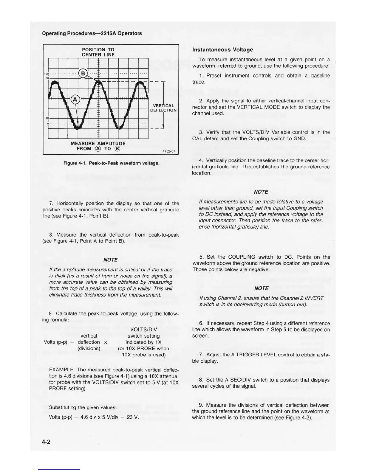
Figure 4-1. Peak-to-Peak waveform voltage.
4732-07
7. Horizonta
ll
y position the display so that one
of
the
positive peaks coincides with the center vertical graticule
line (see Figure
4-1
, Point B).
8. Measure the vertical deflec
ti
on from peak-to-peak
(see Figure
4-1
, Point A
to
Point B).
NOTE
If
the amplitude measurement
is
critical
or
if
the trace
is thick (as a result
of
hum
or
noise
on
the signal), a
more accurate value can be obtained
by
measuring
from the top
of
a peak
to
the top
of
a valley. This will
eliminate trace thickness from the measurement.
9. Calculate the peak-to-peak voltage, using the follow-
ing formul
a:
vertical
Vo
l
ts
(p-p) = deflection x
(divisions)
VOLTS/DIV
switch setting
indicated by 1 X
(or 1
OX
PROBE when
1
OX
probe is used)
EXAMPLE: The measured peak-to-peak vertical deflec-
tion is 4.6 divisions (see Figure 4-1) using a 1
OX
attenua-
tor probe with the VOLTS/DIV switch set
to
5 V (at 1
OX
PROBE setti
ng).
Substituting the given values:
Volts (p-p)
= 4.6 div x 5 V/div = 23 V.
4-2
Instantaneous
Vol
tage
To measure instantaneous level
at
a given point on a
waveform,
re
ferred
to
ground, use the following procedure:
1 . Preset instrument controls and obtain a baseline
trace.
2. Apply the signal
to
either vertical-cha
nn
el input con-
nector and set the VERTICAL MODE switch
to
display the
channel used.
3.
Ver
ify that the VOLTS/DIV Variable control is in the
CAL detent and set the Coupling switch
to
GND.
4. Vertically position the baseline trace
to
the center hor-
izontal graticule line. This establishes the ground reference
location.
NOTE
If
measurements are
to
be
made relative to a voltage
level other than ground,
set
the Input Coupling switch
to
DC
instead, and apply the reference voltage to the
input connector. Then position the trace
to
the refer-
ence (horizontal graticule) line.
5. Set the COUPLING
sw
itch
to
DC. Points on the
waveform above the ground reference location are positive.
Those points below are nega
ti
ve.
NOTE
If
using Channel
2,
ensure that the Channel 2 INVERT
switch is
in
its noninverting mode (button out).
6. If necessary, repeat Step 4 using a different reference
line
wh
i
ch
allows the waveform in Step 5
to
be displayed on
screen.
7. Adjust the A TRIGGER LEVEL control
to
obtain a sta-
ble display.
8. Set the A SEC/DIV switch
to
a position that displays
several cycles
of
the signal.
9. Measure the divisions
of
vertical deflection between
the ground reference line and the poi
nt
on the waveform at
which the level is
to
be determined (see Figure 4-2).

 Loading...


