5. Position the display
to
place the time-measurement
points on the center
hor
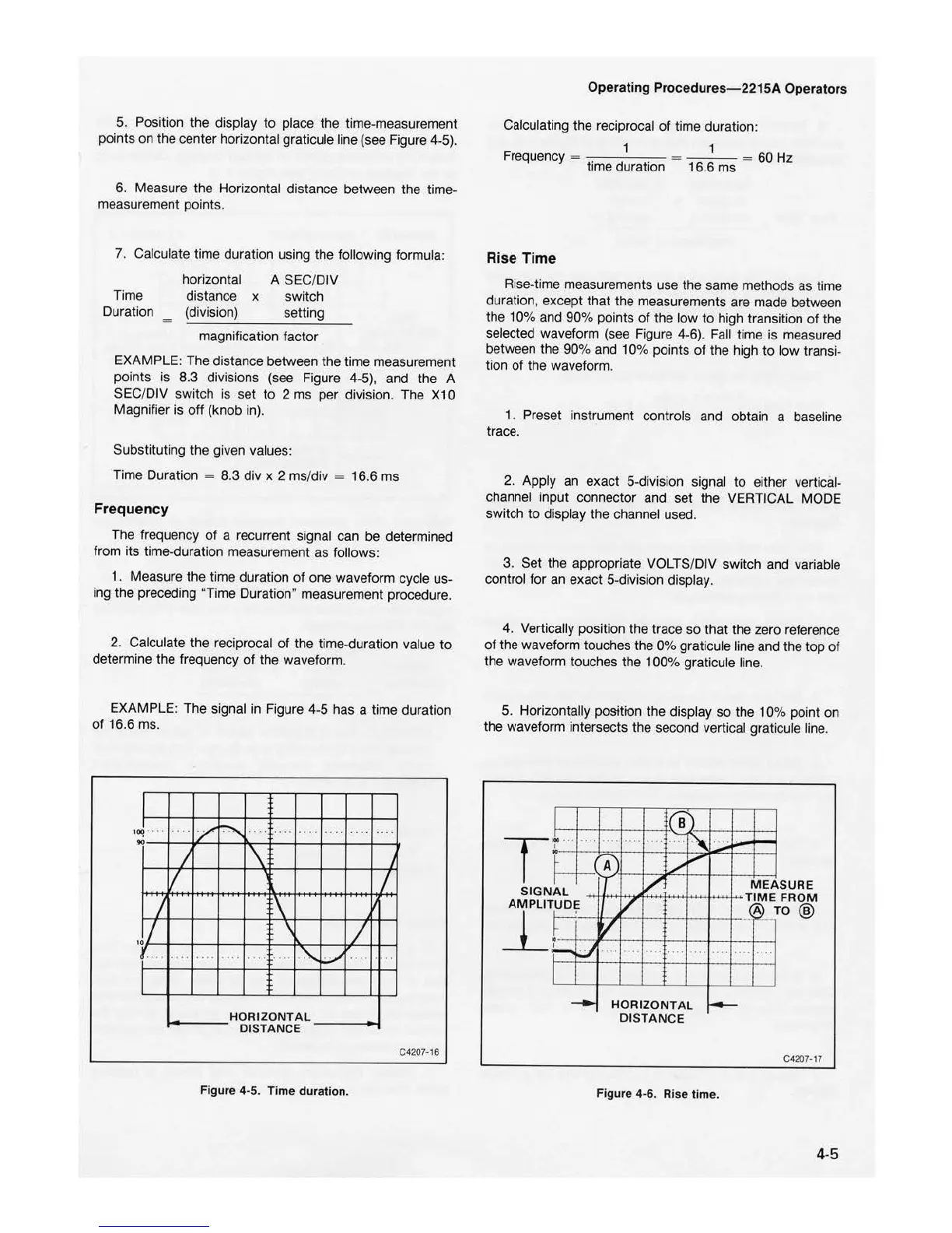
izontal graticule line (see Figure 4-5).
6. Measure the Horizontal distance between the time-
measurement points.
7. Calculate time duration using the following formula:
Ti
me
Duration
horizontal
distance x
(division)
A SEC/DIV
switch
setting
magnification factor
EXAMPLE: The distance between the time measurement
points is 8.3 divisions (see Figure 4-5), and the A
SEC/DIV switch is set
to
2 ms per division. The X10
Magnifier is
off
(knob in).
Substituting the given values:
Time Duration
= 8.3 div x 2 ms/div = 16.6 ms
Frequency
The frequency
of
a recurrent signal can be determined
from
its
time-duration measurement as follows:
1 . Measure the time duration
of
one waveform cycle us-
ing the preceding Duration" measurement procedure.
2. Calculate the reciprocal
of
the time-duration value
to
determine the frequency
of
the waveform.
EXAMPLE: The signal in Figure 4-5 has a time duration
of
16.6 ms.
!
1
00
..
.
..
J
,.I
..
,,
....
I
I
.
,,
.
/
~
. . . , . ...
....
. .
\
J.
1
I
\
'
L
.... .... .
...
.
"\..
~
... ...
HORI
ZONTAL
DISTANCE
C4207•16
Figu
re 4-5.
Time
d
ur
atio
n.
Operating Procedure
s-22
15A Operators
Calculating the reciprocal
of
time duration:
1 1
Frequency = ti
me
duration 16.6 ms =
60
Hz
Rise
Ti
me
Rise-time measurements use the same methods as time
duration, except that the measurements are made between
the
10
% and 90% points
of
the low
to
high transition
of
the
selected waveform (see Figure 4
-6).
Fall time is measured
between the 90%
and
10% poi
nts
of
the high to l
ow
transi-
tion of the waveform.
1. Preset instrument controls and obtain a baseline
trace.
2. Apply an exact 5-division signal
to
either vertical-
channel input connect
or
and set the VERTICAL MODE
switch
to
display the channel used.
3. Set the appropriate VOLTS/DIV switch and variable
control for an exact 5-division displ
ay.
4. Vertically position the trace so that the zero referen
ce
of
the waveform touches the
0%
graticule line and the top
of
the waveform touches the 100% graticule line.
5. Horizontally position the display
so
the 10% point on
the waveform intersects the second vertical graticule l
ine.
I
T
.i.
...
....
I
"
t
SIGN
AM PLIT
~ L
UD
E
_L
h
.
t::
u
I
--
( e
')
....
...
...
.
-
~
A'
/
~
T
/
V
V
....
....
....
...
.
....
H
OR
IZ
ONTA
L
D
ISTANC
E
.
...
-
....
·-
-
ME
A
SU
RE
FROM TIM E
TO
@
..
ce>
--
.
...
··
·•
-
C4207•17
Figure
4-6. R
ise
time.
4-5

 Loading...


