Operating Procedures- 2215A Operators
6. Measure the horizont
al
distance between the 10%
and
90%
po
ints (between Points A and B
of
Figure 4-6) and
calculate the time duration using the following formula:
Rise Ti
me
horizontal
distance x
(divisions)
A
SEC
/DIV
switch
setting
magnification factor
Example: The horizontal distance between the
10
% and
90% points is 5 divisions, and the A SEC/DIV switch is
set to 1
µs
per division. The X10 magnifier knob is off
(knob in).
Substituting the given values in the formula:
R
. 5 div x 1
µ.S
/div
5 ,se ,me
=
1
=
µs
Time Difference Between Pulses On Time-Related
Signals
The calibrated sweep speed and dual-trace features
of
the 2215A allow measurement
of
the time difference be-
tween two separate events.
To
measure time difference,
use the following procedure:
1 . Preset instrument controls and obtain a baseline
trace, then set the A TRIGGER SOURCE
sw
itch
to
CH 1.
2. Set both Input Coupling switches
to
the same posi-
tion, depending on the type
of
input coupling desired.
3. Using either probes
or
cables with equal time delays,
connect a known reference signal
to
the Channel 1 input
and the comparison signal
to
the Channel 2 input.
4. Set both VOLTS/DIV switches for 4-
or
5-division
displays.
5. Select BOTH VERTICAL MODE; then select either
ALT or CHOP, depending on the frequency
of
input signals.
6.
If
the
two
signals are
of
opposite polarity, press in the
Channel 2 INVERT button
to
invert the Channel 2 display
(signals may be
of
opposite polarity due
to
180° phase
differ
ence).
7.
Adjust the A TRIGGER LEVEL control
for
a stable
display.
4-6
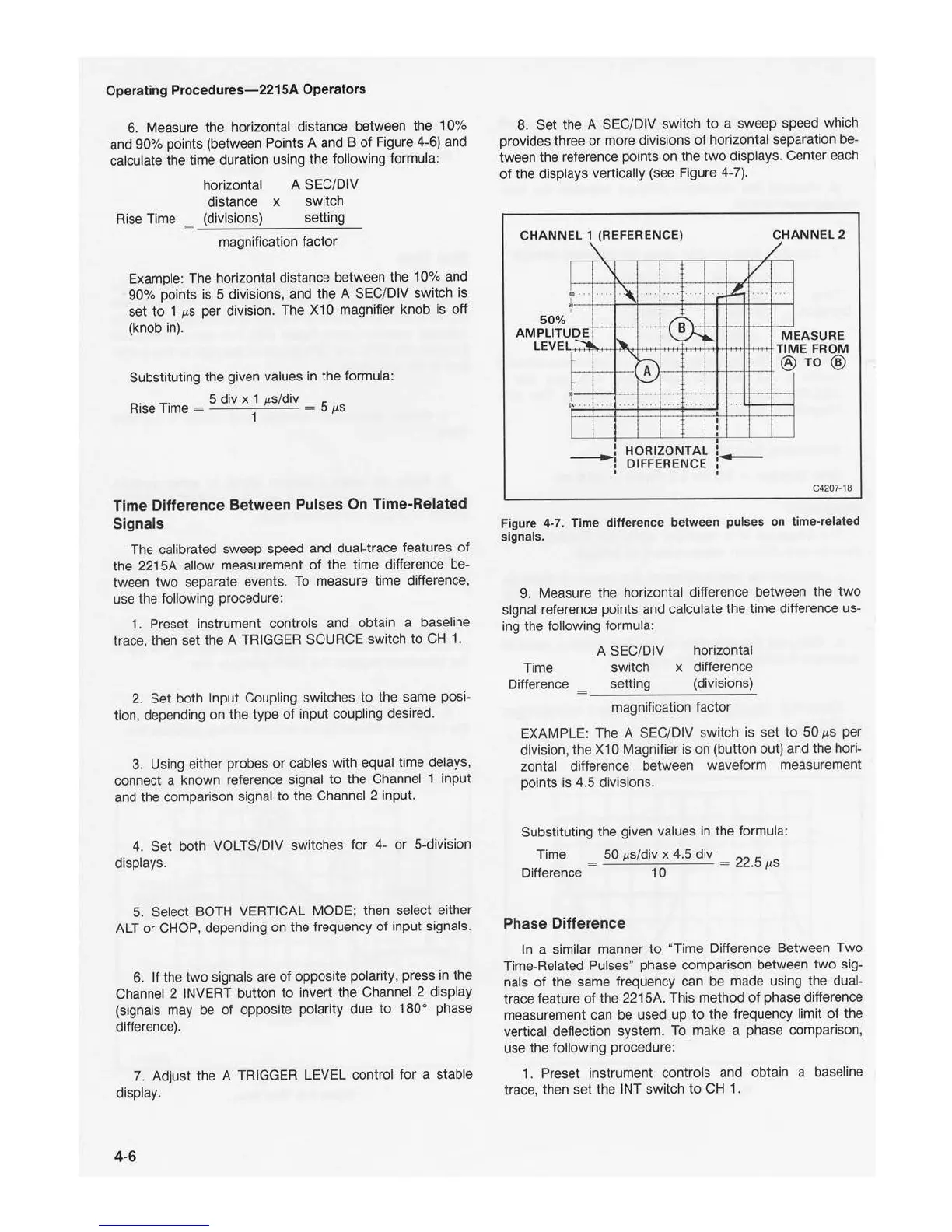
8. Set the A SEC/DIV
sw
itch
to
a sweep speed which
provides three
or
more divisions
of
horizontal separation be-
tween the reference points on the
two
displays. Center each
of
the displays vertically (see Figure 4-7).
CHA
NN
EL 1 (REFERENCE)
...
I
50
%
AMPLITU
LE
VEL
DE
I
.. "
\
....
I
I
I
V
...
....
I
I
I
HORIZO
NT
AL
DIFFERENCE
C
HANN
EL 2
-
M
EA
SUR
E
ME
FR
OM Tl
®
C4207
-1
8
Figure 4-7. Time difference between pul
ses
on time-related
signals.
9. Measure the horizontal difference between the two
signal reference points and calculate the time difference us-
ing the following
fo
rmula:
Time
Difference
A
SEC
/DIV horizontal
switch x difference
setting (divisions)
magnification factor
EXAMPLE: The A SEC/DIV switch is set
to
50
µs
per
division, the X10 Magnifier is on (button out) and the hori-
zontal differen
ce
between waveform measurement
points is 4.5 divisions.
Substituting the given values in the formula:
Time
= 50
µ.S
/div x 4.5 div = 22.5
µs
Difference 1 0
Phase Difference
In
a similar manner
to
"Time Difference Between
Two
Time-Related Pulses' phase comparison between
two
sig-
nals
of
the same frequency can be made using the dual-
trace feature
of
the 2215A. This method
of
phase difference
measurement can be used up
to
the frequency limit
of
the
vertical deflection system.
To
make a phase comparison,
use the following procedure:
1 . Preset instrument controls and obtain a baseline
trace, then set the INT switch
to
CH
1.

 Loading...


