Operating Procedures- 2215A Operators
CH1 S
IGNA
L -
WIT
H
UNWANTE
D
CH2
SIGNAL
FROM LINE
FREQUENCY
SO
URCE
(A)
CH1
AND
CH2
SIGNALS
.
I
...
I
---------
SIGNAL
WIT
H
LINE FREQUE
NCY
COMP
ON
E
NT
CANCELED
OUT
I
...
....
..
.
",.
(Bl RESULTANT
SIGNAL.
4732
-09
Figure 4-3. Common-mode rejection.
7. Select ADD VERTICAL MODE and press in the
INVERT button, and slightly readjust the
CH
2 VOLTS/DIV
Variable control for maximum cancellation
of
the undesired
signal component (see Figure 4-38).
Amplitude Comparison (Ratio)
In some app
li
cations it may be necessary
to
establish a
set of deflection factors other than those indicated by the
VOLTS/DIV switch settings. This is useful for comparing
unknown signals
to
a reference signal
of
known amplitude.
To
accomplish this, a reference signal
of
known amplitude is
first set to
an
exact number
of
vertical divisions by adjusting
the
VOLTS
/DIV switch and Variable control. Unknown sig-
nals can then be quickly and accurately compared with the
reference signal without disturbing the setting
of
the
VO
LTS/DIV Variable control. This procedure is as follows:
1 . Preset instrument controls
and
ob
ta
in
a baseline
trace.
2. Apply the reference signal
to
either vertical channel
input
and
set the VERTICAL MODE switch
to
display the
channel used.
3. Set the amplitude
of
the reference sign
al
to
five verti-
cal divisions by adjusting the VOLTS/DIV swi
tc
h and
VOLTS
/DIV Variable control.
4-4
-
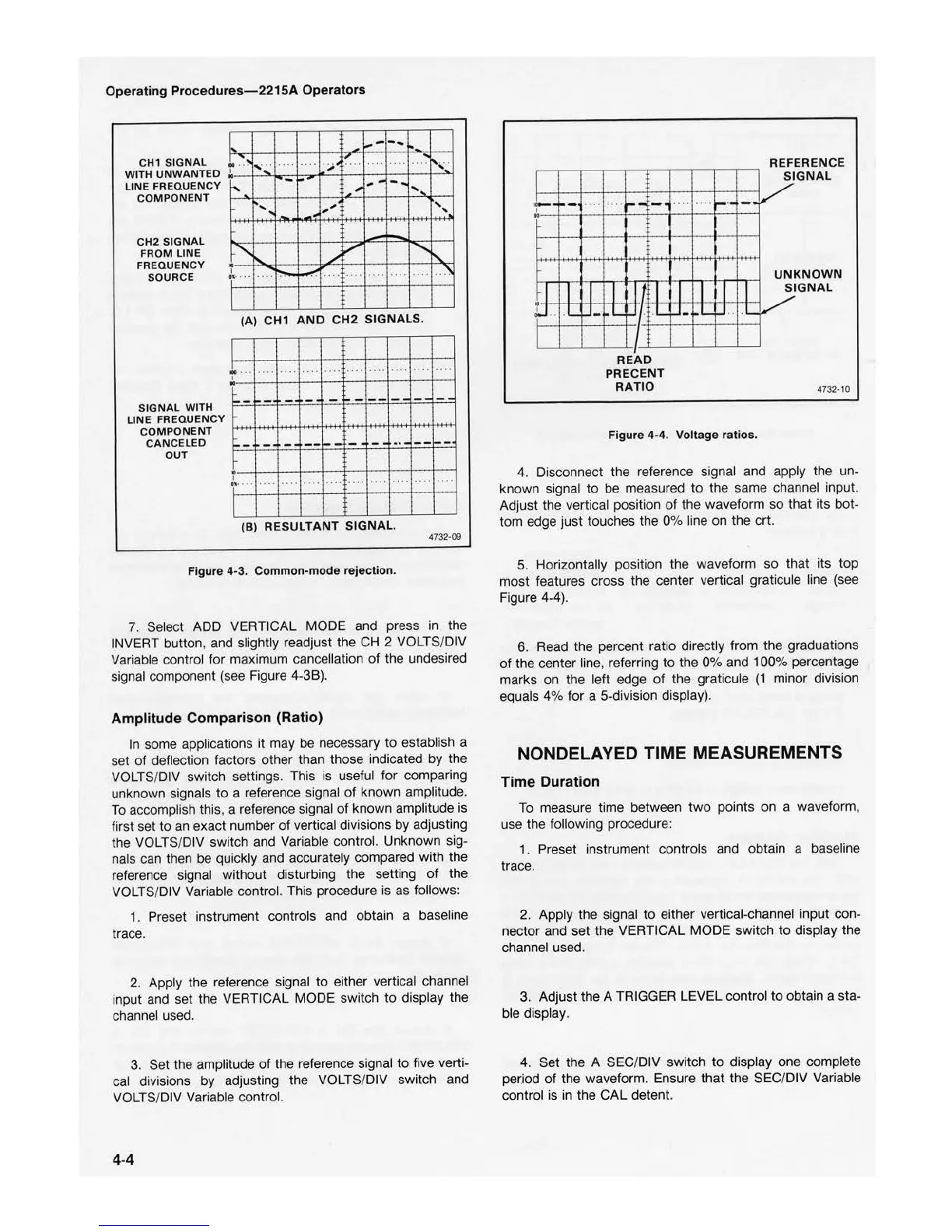
READ
PRECENT
RATIO
Figure 4-4.
Vo
lt
age ratios.
REFERENCE
SIGNAL
UNKNOWN
SI
GNAL
4732-10
4. Disconnect the reference signal and apply the un-
known signal
to
be measured
to
the same channel input.
Ad
just the vertical position
of
the waveform so that its bot-
tom edge just touches the 0% line on the crt.
5. Horizontally position the waveform so that
its
top
most features cross the center vertical graticule line (see
Figure
4-4).
6. Read the percent ratio directly from the graduations
of
the center line, referring
to
the 0% and 100% percentage
marks on the left edge
of
the graticule
(1
minor division
equals 4%
for
a 5-division display).
NONDELAYED TIME MEASUREMENTS
Time
Duration
To
measure time between
two
points on a waveform,
use the following procedure:
1 . Preset instrument controls and obtain a baseline
trace.
2. Apply the signal
to
either vertical-channel input con-
nec
to
r and set the VERTICAL MODE switch
to
display the
channel used.
3. Adjust the A TRIGGER LEVEL control
to
obtain a sta-
ble display.
4. Set the A SEC/DIV switch
to
display one complete
period
of
the waveform. Ensure that the SEC/DIV Variable
control is in the CAL detent.

 Loading...


