Operators Familiarization
-22
15A Operators
PROBE
COMPENSATION
Misadjustment
of
probe compensation is a common
source
of
measurement error. Most attenuator probes are
equipped with a compensation adjustment.
To
ensure opti-
mum measurement accuracy, always compensate the oscil-
loscope probes before making measurements. Probe
compensation is accomplished as follows:
1 . Preset instrument controls and obtain a baseline
trace.
2. Connect the two 10X probes (supplied with the instru-
ment)
to
the
CH
1 and CH 2 input connectors.
3. Set both VOLTS/DIV switches
to
10 mV and set both
Input Coupling switches
to
DC.
4. Select
CH
1 VERTICAL MODE and insert the tip
of
the Channel 1 probe into the PROBE ADJUST output jack.
5. Using the approximately 1 kHz PROBE ADJUST
square-wave signal as the input, obtain a 5-division display
of the signal.
6. Set the A SEC/DIV switch
to
display several cycles
of
the PROBE ADJUST signa
l.
Use the Channel 1 POSITION
control to vertically center the display.
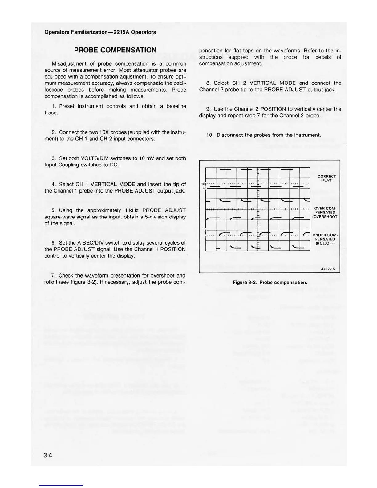
7. Check the waveform presentation for overshoot and
rolloff (see Figure 3-2).
If
necessary, adjust the probe com-
3-4
pensation
for
flat tops on the waveforms. Refer
to
the in-
structions supplied with the probe
for
details of
compensation adjustment.
8.
Select
CH
2 VERTICAL MODE and connect the
Channel 2 probe tip
to
the PROBE ADJUST output jack.
9. Use the Channel 2 POSITION
to
vertically center the
display and repeat step 7 for the Channel 2 probe.
10. Disconnect the probes from the instrument.
CORRECT
(FLAT)
OVER
COM-
PENSATED
IOVE
RSHOOTI
Figure 3-2. Probe compens
at
ion.
UNDER
COM
-
PENSATED
(
RO
LLO
Ff
I
4732-
15

 Loading...


