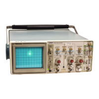
Operating Procedure
s-
221
SA
Op
erators
TELEVISION DISPLAYS
TV
Line Signal
The following procedure is used
to
display a TV Line
signa
l.
1. Preset instrument controls and select P-P
AU
TO/TV
LINE A TRIGGER Mode.
2. Apply the TV signal
to
either vertical-channel input
connector and set the VERTICAL MODE switch
to
display
the channel used.
3. Set the appropriate VOLTS/DIV switch
to
display 0.3
division
or
more
of
composite sync signal.
4. Set the A SEC/DIV switch
to
10
µs.
5. For positive-going TV signal sync pulses, set the
A TRIGGER SLOPE switch
to
OUT and adjust the
A TRIGGER LEVEL control
to
its fully clockwise position;
for negative-going TV signal sync pulses, set the
A
TR
I
GGER
SLOPE switch
to
IN and adjust the
A
TR
I
GGER
LEVEL control
to
its fully counterclockwise
position.
NOTE
To
examine a
TV
Line signal in more detail, either the
X10 Magnifier
or
the Delayed-Sweep Magnification
feature may be used.
TV
Field Signal
The television feature
of
the 2215A can al
so
be used
to
display TV Field signals.
1. Preset instrument controls and obta
in
a baseline
trace.
2. Select TV FIELD A TR
IG
GER mode (push both P-P
AUTO and NORM buttons in) and set the A SEC/DIV switch
to
2 ms.
3.
To
display a signal field, connect the TV signal
to
ei-
ther vertical-channel input connector and set the
VE
RTICAL
MODE switch
to
display the channel used.
4-8
4. Set the appropriate VOLTS/DIV switch
to
display
1-division
or
more
of
composite sync signa
l.
5. For positive-going TV signal sync pulses, set the A
TRIGGER SLOPE switch
to
OUT and adjust the A TRIG-
GER LEVEL control
to
its fully clockwise position; for nega-
tive-going TV signal sync pulses, set the A TRIGGER
SLOPE switch
to
IN
and adjust the A TRIGGER LEVEL
control
to
its fully counterclockwise position.
6.
To
change the TV field that is displayed, momentarily
interrupt the
tr
igger signal by setting the Input Coupling
switch
to
GND and then back
to
DC
or
AC until the desired
f
ie
ld is displayed.
NOTE
To
examine a TV Field signal in more detail, either the
X10 Magnifier
or
the Delayed-Sweep Magmfication
feature may be used.
7.
To
display a selected horizontal line, first trigger the
sweep on a vertical (field) sync pulse, then use the "Magni-
fied Sweep Runs After Delay· procedure in this part (steps 5
th
rough
7)
to magnify the selected horizontal line
for
a closer
examination. This procedure is useful for examining Vertical
Interval Test Signals (VITS).
8.
To
display either Field 1 or Field 2 individually, con-
nect the TV signal
to
both
CH
1 and CH 2 input connectors
and select BOTH and A
LT
VERTICAL
MO
DE. Set the
A
SEC
/DIV switch
to
0.5 ms
or
faster sweep speed (dis-
plays less than one full field). This will synchronize Channel
1 display
to
one field and Channel 2
to
the other field.
DELAYED-SWEEP MAGNIFICATION
The delayed-sweep feature of the 2215A can be used
to
provide higher apparent magnification than is provided by
the
X1
O Magnifier switch. Apparent magnification occurs as
a result
of
displaying a selected portion
of
the A trace at a
faster sweep speed (B Sweep speed). The A SEC/DIV
switch setting determines how often the B trace wi
ll
be dis-
played. Since the B Sweep can occur only once for each A
Sweep, the A Sweep time duration sets the amount
of
time
elapse between succeeding B Sweeps.
The intensified zone is an indication
of
both the location
and length
of
the B Sweep interval within the A Sweep inter-
val. Positioning
of
the intensified zone (i.e., setting the

 Loading...