2.
Set
both
Input Coupling
sw
itches
to
the same posi-
tion, depending
on
the
type
of
input coupling desired.
3.
Using either probes
or
cables wi
th
equal time delays,
connect a known reference sign
al
to
the Channel 1 input
and
the
unknown signal
to
the Channel 2 input.
4. Select BOTH VERTICAL MODE; then select either
ALT
or
CHOP, depending
on
the frequen
cy
of
i
nput
signals.
The reference signal should precede
the
comparison signal
in time.
5.
If
the
two
signals are
of
opposite polarity, press in the
Channel 2 INVERT button
to
invert the Channel 2 display.
6. Set both VOLTS/DIV switches and
both
Variable con-
trols
so
the displays are equal
in
amplitude.
7. Adjust
the
A TRIGGER LEVEL control for a stable
display.
8. Set the A SEC/DIV
sw
itch
to
a sweep speed
wh
ich
displays about one fu
ll
cycle
on
the waveforms.
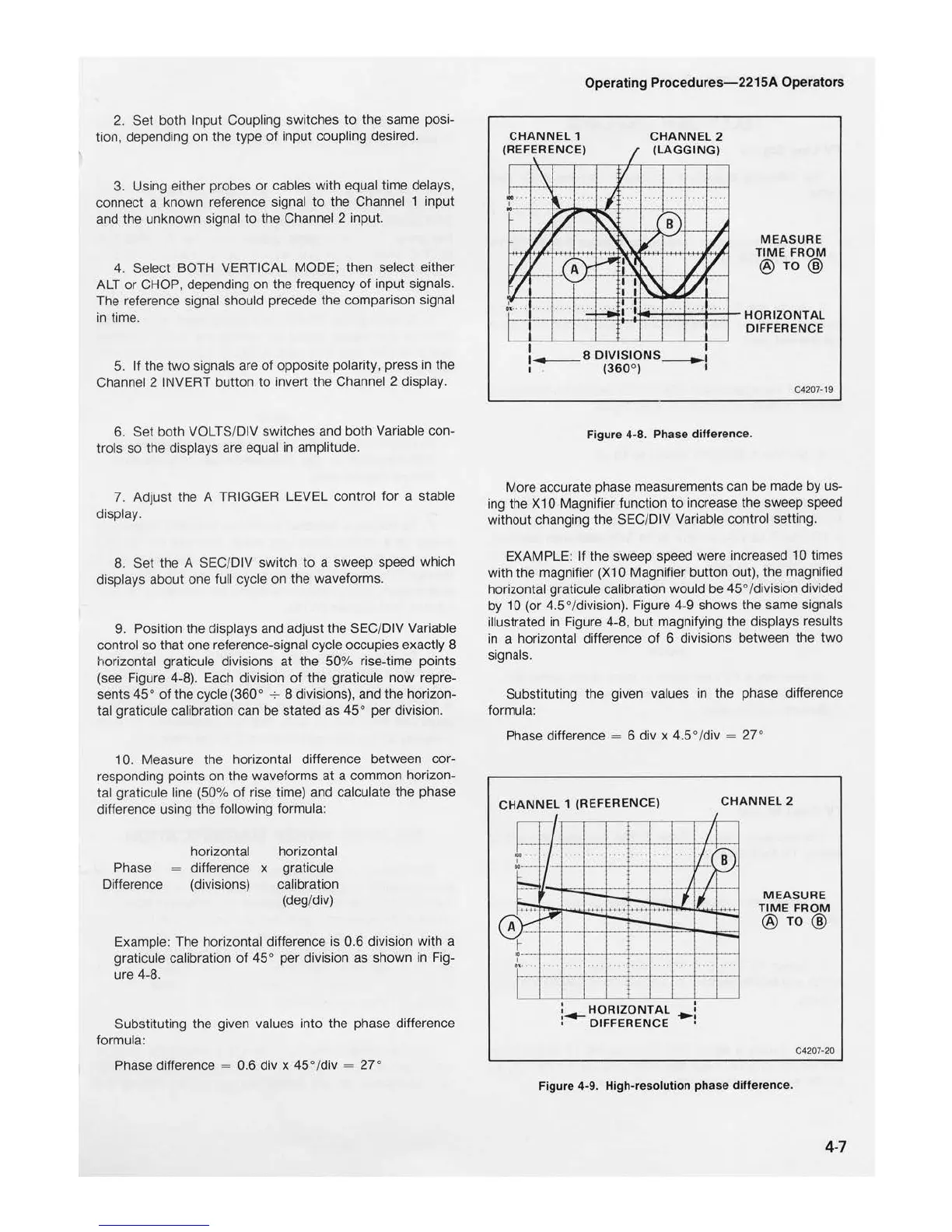
9. Position
the
displays and adjust the SEC/DIV Variable
control
so
that
one reference-signal cycle occupi
es
exactly 8
horizontal graticule divisions
at
the
50%
rise-time points
(see Figure 4-8). Each division
of
the
graticule
now
repre-
sents
45
°
of
the cycle (360° 8 divisions), and the horizon-
ta
l graticule calibration can
be
stated
as
45
° per division.
10. Measure the horizontal difference between cor-
responding points
on
the waveforms
at
a common horizon-
tal
grat
icule line (50%
of
rise time) and calculate the phase
difference using
the
following formula:
Phase
Difference
horizontal
difference x
(divisions)
horizontal
graticule
calibration
(deg/div)
Example: The horizontal difference
is
0.6 division with a
graticule calibration
of
45
° per division as shown in Fig-
ure 4-8.
Substituting the given values
into
the phase difference
formula:
Phase difference 0.6 div x
45°
/div
27°
Operating
Procedures-2215A
Operators
CHANNEL
2
(LAGGI
NG)
I I
DIVISIONS__.,1
I
(360
°)
Figure 4-8. Phase difference.
M EASURE
TIM
E
FROM
C4207
-19
More accurate phase measurements can be made
by
us-
ing the X 1 0 Magnifier function
to
increase the sweep speed
without changing the SEC/DIV Variable control setting.
EXAMPLE:
If
the sweep speed were increased 10 times
with the magnifi
er
(X10 Magnifier button out), the magnified
horizontal graticule
ca
li
bration would be
45
° /division divided
by
10 (or
4.5°/d
ivision). Figure 4-9 shows the same signals
illustrated in Figure 4-8,
but
magnifying
the
displays results
in a horizontal difference
of
6 divisions between the
two
signals.
Substituting the given values in the phase difference
formula:
Phase difference
= 6 div x 4.5
°/
div 27°
CHAN
NEL
1 (
REF
ERENCE)
HORIZONTAL
DIFFERENCE
CHANNEL
2
ME
ASURE
TIME
FROM
C4207-20
Figure
4-9
. H
igh-resol
utio
n
phase
differen
ce.
4-7

 Loading...


