amount of time between start
of
the A Sweep
and
start
of
the B Sweep) is accomplished with the B
DELAY
TIME PO-
SITION control. With either ALT
or
B HORIZONTAL MODE
selected and B TRIGGER LEVEL control set fully clockwise
(BRUNS
AFTER
DLY)
, the B DELAY TIME POSITION con-
trol provides continuously variable positioning
of
the start
of
the B Sweep. The range
of
this control is sufficient
to
place
the B Sweep interval
at
most any location within the A
Sweep interval. When ALT HORIZONTAL MODE is se-
lected, the B SEC/DIV switch setting determines the B
Sweep speed and concurrently sets the length of the inten-
sified zone on the A trace.
Using delayed-sweep magnification may produce a dis-
play with some slight horizontal movement (pulse jitter).
Pulse jitter includes not only the inherent uncertainty
of
trig-
gering the delayed sweep
at
exactly the same trigger point
each time, but also jitter that may be present in the input
signal. If pulse jitter needs
to
be measured, use the "Pulse
Jitter Time Measurement· procedure which follows the dis-
cussion
of
"Magnified Sweep Runs After Delay."
Magnified Sweep Runs After Delay
The following procedure explains how
to
operate the B
Sweep in a nontriggered mode and to determine the result-
ing apparent magnification factor.
1. Preset instrument controls and obtain a baseline
trace.
2. Apply the signal
to
either vertical channel input con-
nector and set the VERTICAL MODE switch
to
display the
channel used.
3. Set the appropriate VOLTS/DIV
sw
itch
to
produce a
display
of
approximately 2-
or
3-divisions in amplitude and
center the display.
4.
Set the A SEC/DIV switch
to
a sweep speed which
displays at least one complete waveform cycle.
5. Select ALT HORIZONTAL MODE. Adjust both the
appropriate channel POSITION control and the A/B SWP
SEP
control
to
display the A trace above the B trace.
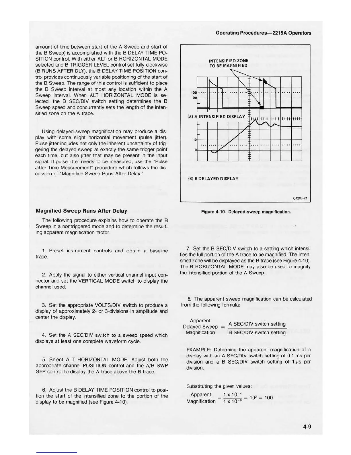
6. Adjust the B DELAY TIME POSITION control
to
posi-
tion the start
of
the intensified zone
to
the portion
of
the
display to be magnified (see Figure
4-10).
Operating Procedure
s-22
15A Operators
0
••••
10
9
INTENSIFI
ED
ZONE
TO BE MAGNIFIED
""
...
.
...
...
(A)
A INTENSIFIED DISPLAY
V
0
....
....
.
...
..
..
0
(B) B
DELAYED
DISPLAY
. .
..
..
..
. ...
....
....
Figure 4•10. Delayed-s
weep
magnification.
....
....
C4
20
7·21
7.
Set the B
SEC
/DIV switch
to
a setting which intensi-
fies the full portion
of
the A trace
to
be magnified. The inten-
sified zone will be displayed as the B trace (see Figure
4-10).
The B HORIZONTAL MODE may also be used
to
magnify
the intensified portion
of
the A Sweep.
8.
The apparent sweep magnifica
ti
on can be calculated
from the following formula:
Apparent
De
layed Sweep
Magnification
A SEC/DIV switch setting
B
SEC
/D IV switch setting
EXAMPLE: Determine the apparent magnification of a
display with an A SEC/DIV switch setting
of
0
.1
ms per
division and a B SEC/DIV switch setting
of
1
µs
per
division.
Substitut
in
g the given values:
Apparent
= 1 x
10
4 =
10
2
=
100
Magnification 1 x 1 0 -6
4-9

 Loading...


