Theory of Operation-314 Service
EMITTER-
COMMON-
SIGNAL
INPUT
OUTPUT
\MP
TO LEFT
DEFLECTION
PLATE
TO RIGHT
DEFLECTION
PLATE
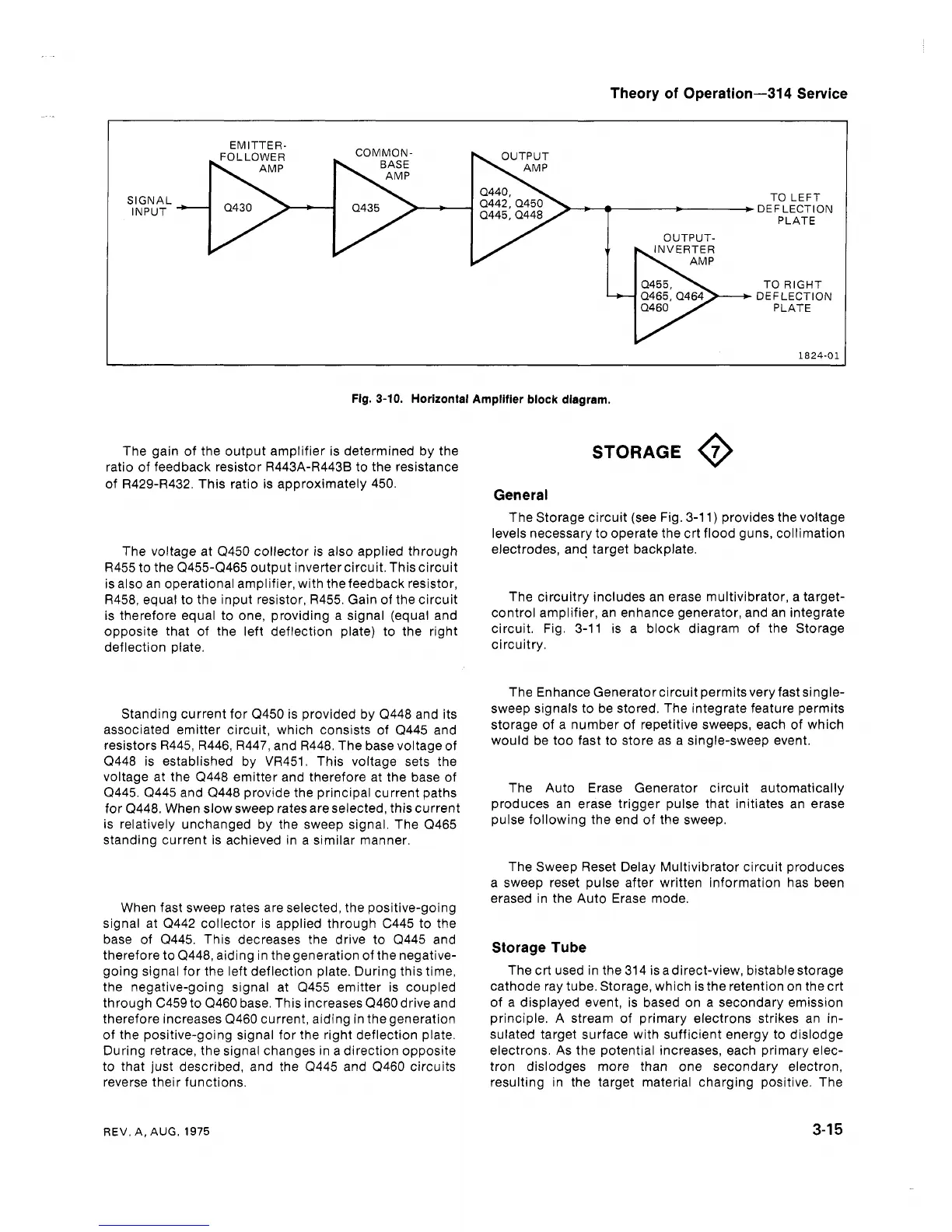
Fig. 3-10. Horizontal Amplifier block diagram.
The gain of the output amplifier is determined by the
ratio of feedback resistor R443A-R443B to the resistance
of
R4294432. This ratio is approximately 450.
The voltage at Q450 collector is also applied through
R455 to the Q455-(2465 output inverter circuit. This circuit
is also an operational amplifier, with the feedback resistor,
R458, equal to the input resistor, R455. Gain of the circuit
is therefore equal to one, providing a signal (equal and
opposite that of the left deflection plate) to the right
deflection plate.
Standing current for Q450 is provided by (2448 and its
associated emitter circuit, which consists of (2445 and
resistors R445, R446, R447, and R448. The base voltage of
(2448 is established by VR451. This voltage sets the
voltage at the Q448 emitter and therefore at the base of
(2445. Q445 and Q448 provide the principal current paths
for Q448. When slow sweep rates are selected, this current
is relatively unchanged by the sweep signal. The Q465
standing current is achieved in a similar manner.
When fast sweep rates are selected, the positive-going
signal at Q442 collector is applied through C445 to the
base of
Q445. This decreases the drive to Q445 and
therefore to
(2448, aiding in thegeneration of the negative-
going signal for the left deflection plate. During this time,
the negative-going signal at Q455 emitter is coupled
through C459 to (2460 base. This increases Q460 drive and
therefore increases Q460 current, aiding in the generation
of the positive-going signal for the right deflection plate.
During retrace, the signal changes in a direction opposite
to that just described, and the Q445 and (2460 circuits
reverse their functions.
STORAGE
@
General
The Storage circuit (see Fig. 3-1 1) provides the voltage
levels necessary to operate the crt flood guns, collimation
electrodes, and target backplate.
The circuitry includes an erase multivibrator, a target-
control amplifier, an enhance generator, and an integrate
circuit. Fig. 3-11 is a block diagram of the Storage
circuitry.
The Enhance Generator circuit permitsvery fast single-
sweep signals to be stored. The integrate feature permits
storage of a number of repetitive sweeps, each of which
would be too fast to store as a single-sweep event.
The Auto Erase Generator circuit automatically
produces an erase trigger pulse that initiates an erase
pulse following the end of the sweep.
The Sweep Reset Delay Multivibrator circuit produces
a sweep reset pulse after written information has been
erased in the Auto Erase mode.
Storage Tube
The crt used in the 314 is adirect-view, bistablestorage
cathode ray tube. Storage, which is the retention on the crt
of a displayed event, is based on a secondary emission
principle. A stream of primary electrons strikes an in-
sulated target surface with sufficient energy to dislodge
electrons. As the potential increases, each primary elec-
tron dislodges more than one secondary electron,
resulting in the target material charging positive. The
REV. A, AUG.
1975
 Loading...


