Maintenance-314 Service
Troubleshooting Techniques
This troubleshooting procedure is arranged to check
the simple trouble possibilities before proceeding with
extensive procedures. The first few checks ensure proper
connections, operation, and calibration. If the trouble is
not located by these checks, the remaining steps aid in
locating defective components.
1. Check Control Settings.
lncorrect control settings
can indicate a trouble that does not exist. If there is any
question about the correct function or operation of any
control, see the Operators Manual.
2. Check Associated Equipment.
Before proceeding
with troubleshooting, be certain that the equipment used
with the 314 is operating and connected correctly. Check
for a defective power supply and interconnecting cables.
3.
Visual Check.
Many troubles (such as unsoldered
connections, broken wires, damaged circuit boards,
damaged components, etc.) can be located by visual
inspection.
4. Check Instrument Calibration.
Check the calibra-
tion of the instrument, or the affected circuit if the trouble
appears to be in one circuit. The apparent trouble may be a
result of misadjustment and may be corrected by readjust-
ment. Complete adjustment instructions are given in the
Adjustment Procedure.
5.
Isolate Trouble to a Circuit.
To isolate trouble to a
circuit, note the trouble symptom. The symptom often
identifies the circuit in which the trouble is located. For
example, poor focus indicates that the crt circuit is
probably at fault. When trouble symptoms appear in more
than one circuit, check the affected circuits by checking
voltages.
lncorrect operation of all circuits often indicates trou-
ble in the power supply. Check first for correct voltagesof
the individual supplies and determine if one or more
supplies is out of regulation. However, a defective compo-
nent elsewhere in the instrument can appear as a
power-
supply trouble and may affect operation of other circuits.
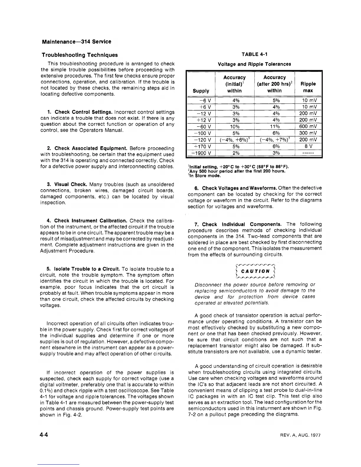
If incorrect operation of the power supplies is
suspected, check each supply for correct voltage (use a
digital voltmeter, preferably one that is accurate to within
0.1%) and check ripple with a test oscilloscope. See Table
4-1 for voltage and ripple
tolerqnces. The voltages shown
in Table 4-1 are measured between the power-supply test
points and chassis ground. Power-supply test points are
shown in Fig. 4-2.
TABLE 4-1
Voltage and Ripple Tolerances
Accuracy Accuracy
(initial)' (after 200 hrs)' Ripple
supply within within
+6
V
3
Oh
4% 10 mV
'Initial setting,
+20° C
to
+30°C (68'F
to
86OF).
'~ny
500
hour period after the first
200
hours.
"n
Store mode.
6.
Check Voltages and Waveforms.
Often the defective
component can be located by checking for the correct
voltage or waveform in the circuit. Refer to the diagrams
section for voltages and waveforms.
7.
Check Individual Components.
The following
procedure describes methods of checking individual
components in the 314. Two-lead components that are
soldered in place are best checked by first disconnecting
one end of the component. This isolates the measurement
from the effects of surrounding circuits.
CAUTION
a
Disconnect the power source before removing or
replacing semiconductors to avoid damage to the
device and for protection from device cases
operated at elevated potentials.
A good check of transistor operation is actual perfor-
mance under operating conditions. A transistor can be
most effectively checked by substituting a new compo-
nent or one that has been checked previously. However,
be sure that circuit conditions are not such that a
replacement transistor might also be damaged. If sub-
stitute transistors are not available, use a dynamic tester.
A good understanding of circuit operation is desirable
when troubleshooting circuits using integrated circuits.
Use care when checking voltages and waveforms around
the
IC's so that adjacent leads are not short circuited. A
convenient means of clipping a test probe to dual-in-line
IC packages in with an IC test clip. This test clip also
serves as an extraction
tool.The lead configuration forthe
semiconductors used in this insturment are shown in Fig.
7-2 on a pullout page preceding the diagrams.
REV.
A,
AUG.
1977
 Loading...


