Maintenance-314 Service
c. Unplug one 5-pin connector (from P537) and one3-
pin connector (from P565) on the Storage circuit board.
d. Unsolder the blue-blue-on-gray shielded leadsfrom
the Store switch terminals.
e. To replace, reverse the foregoing procedure.
Horizontal Circuit Board (Assembly A4)
a. Leave the cam switch screws (through the Storage
circuit board) in place to maintain cam block assembly
alignment.
b. Unsolder the RESET button leadsfrom the Horizon-
tal circuit board.
c. Remove the TIME/DIV knob.
d. Loosen
2
set screws in front half of the flexible
coupling on the end of Variable (CAL) shaft and remove
the shaft through the front panel.
e. Remove POSITION and SWEEP MAG knobs.
f. Remove ENHANCE LEVEL and VIEWING TIME
knobs.
g. Remove hex nuts holding the Position, Sweep Mag,
and Enhance Level controls.
h. Remove the front panel and overlay.
i. Disconnect all connectors and record the P number
to which each was connected.
j.
Remove the Integrate switch from the sub-panel
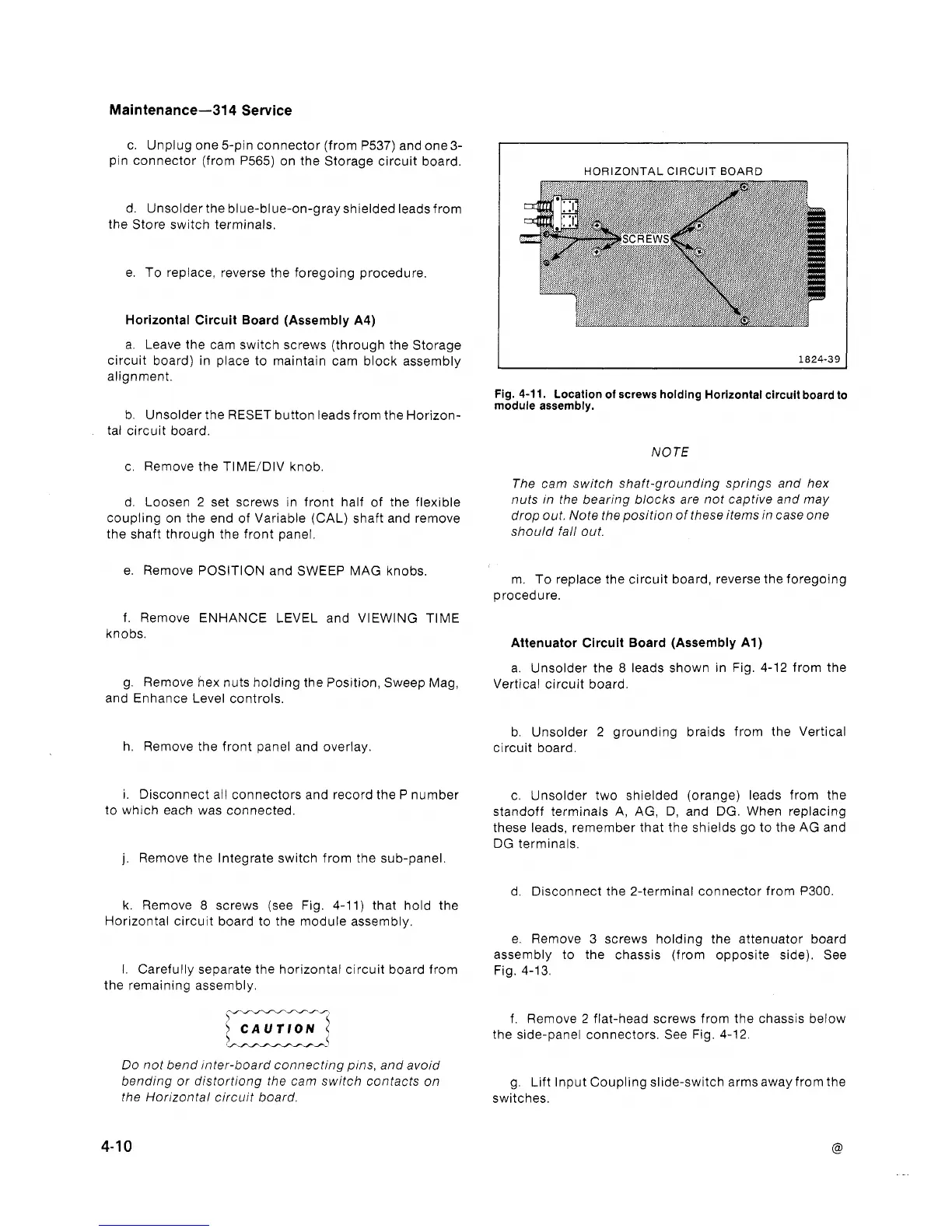
k. Remove
8
screws (see Fig. 4-11) that hold the
Horizontal circuit board to the module assembly.
I.
Carefully separate the horizontal circuit board from
the remaining assembly.
Do not bend inter-board connecting pins, and avoid
bending or distortiong the cam switch contacts on
the Horizontal circuit board.
HORIZONTAL CIRCUIT BOARD
Fig.
4-11.
Location of screws holding Horizontal circuit board to
module assembly.
NOTE
The cam switch shaft-grounding springs and hex
nuts in the bearing blocks are not captive and may
drop out. Note the position of these items in case one
should fall out.
m. To replace the circuit board, reverse the foregoing
procedure.
Attenuator Circuit Board (Assembly Al)
a. Unsolder the
8
leads shown in Fig. 4-12 from the
Vertical circuit board.
b. Unsolder 2 grounding braids from the Vertical
circuit board.
c. Unsolder two shielded (orange) leads from the
standoff terminals A, AG, D, and DG. When replacing
these leads, remember that the shields go to the AG and
DG terminals.
d. Disconnect the 2-terminal connector from
P300.
e. Remove 3 screws holding the attenuator board
assembly to the chassis (from opposite side). See
Fig. 4-13.
f. Remove 2 flat-head screws from the chassis below
the side-panel connectors. See Fig. 4-12.
g.
Lift Input Coupling slide-switch arms away from the
switches.
 Loading...


