Maintenance-314 Service
h.
Lift the rear of the Attenuator circuit board away
from the instrument. When cam switch cover clears the
chassis, pull the board assembly away from the front
panel.
i. To replace the circuit board, reverse the foregoing
procedure.
Vertical Circuit Board
(Assembly A2)
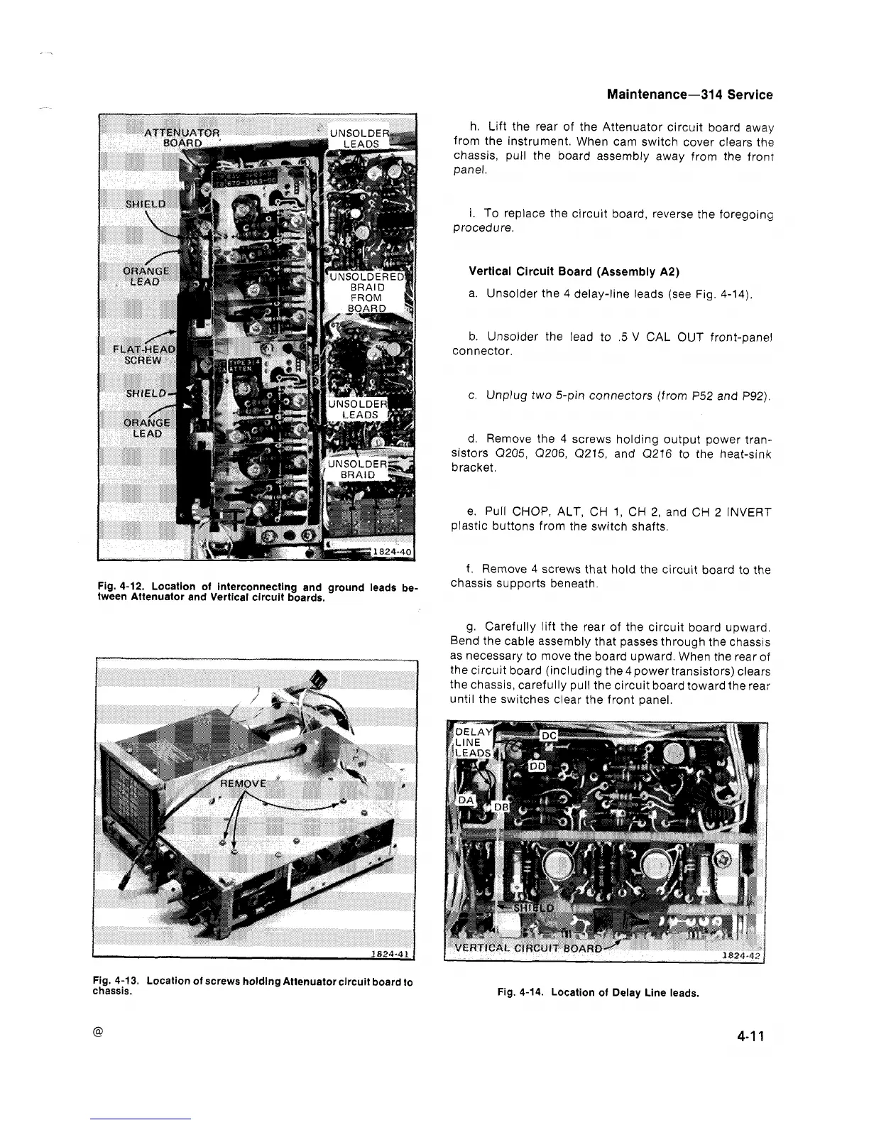
a. Unsolder the 4 delay-line leads (see Fig. 4-14).
b. Unsolder the lead to
.5
V
CAL OUT front-panel
connector.
c. Unplug two 5-pin connectors (from
P52
and
P92).
d. Remove the
4
screws holding output power tran-
sistors
Q205, (2206, (2215,
and
Q216
to the heat-sink
bracket.
e. Pull CHOP, ALT, CH
1,
CH
2,
and CH
2
INVERT
plastic buttons from the switch shafts.
f.
Remove 4 screws that hold the circuit board to the
Fig. 4-12. Location of interconnecting and ground leads be-
chassis
supports beneath.
tween Attenuator and Vertical circuit boards.
g. Carefully lift the rear of the circu~t board upward.
Bend the cable assembly that passes through the chassis
t
-
as necessary to move the board upward When the rear of
*
I
the circ~~t board (inclhding the 4power transistors) clears
u-
the chassis, caref~lly pull the circuit boarcl toward tne rea,
until the switches clear the front panel.
Fig. 4-13. Location of screws holding Attenuator circuit board to
chassis.
Fig. 4-14. Location of Delay Line leads.
@
 Loading...


