Maintenance-314 Service
f. Remove the Power Supply circuit board very careful-
ly to prevent damage to the power transistors mounted on
the heat-sink bracket.
g. To replace, reverse the foregoing procedure
H
V
&
Unblank Circuit Board (Assembly A6)
a. Remove the
3
threaded hexagonal spacers.
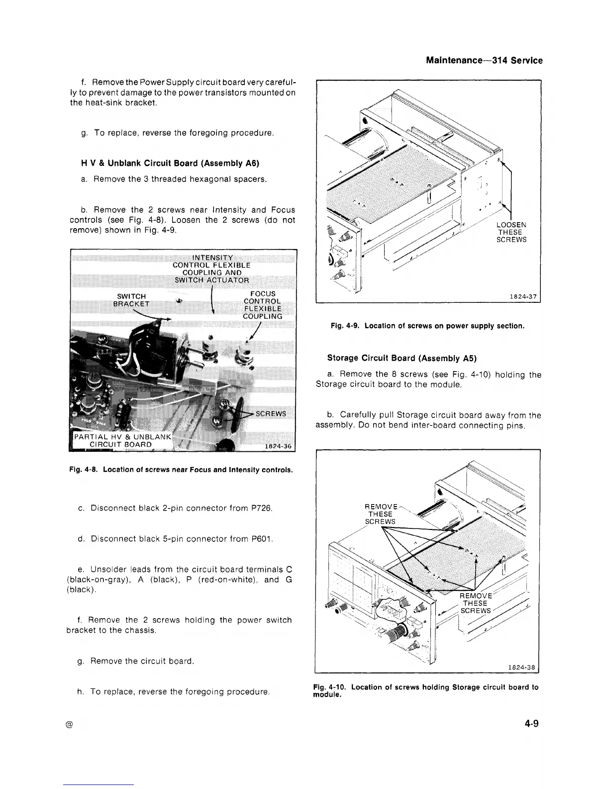
b. Remove the 2 screws near Intensity and Focus
controls (see Fig. 4-8). Loosen the 2 screws (do not
remove) shown in Fig. 4-9.
Fig.
4-9.
Location of screws on power supply section.
Fig.
4-8.
Location of screws near Focus and Intensity controls.
c. Disconnect black 2-pin connector from P726
d. Disconnect black 5-pin connector from P601
e. Unsolder leads from the circuit board terminals
C
(black-on-gray),
A
(black), P (red-on-white), and
G
(black).
f. Remove the 2 screws holding the power switch
bracket to the chassis.
g. Remove the circuit board.
Storage Circuit Board (Assembly
A5)
a. Remove the
8
screws (see Fig. 4-10) holding the
Storage circuit board to the module.
b. Carefully pull Storage circuit board away from the
assembly. Do not bend inter-board connecting pins.
I
h. To replace, reverse the foregoing procedure.
Fig.
4-10.
Location of screws holding Storage circuit board to
module.
4-9