Performance Check/Calibration-314 Service
7. Adjust CH 1 Gain
Set controls as follows:
CH 1 and CH 2
VOLTS/DIV 10 m
VARIABLE CAL
lnput Coupling
CH 1 DC
CH
2
GND
DISPLAY CH 1
CHOP and ALT out
a. Connect Standard Amplitude Calibrator through
50-ohm cable to CH 1 and CH 2 VERT INPUT connectors
via Dual lnput Cable.
b. Set Standard Amplitude Calibrator for 50 mV
square-wave.
c. Check for 5 divisions of vertical deflection,
f3%
(0.75 minor division).
d. ADJUST-R43 (see Fig. 7-4), Gain, for exactly 5
divisions of vertical deflection. For SN 300422-up, switch
CH 1
VOLTS/DIV to 1 mV and standard amplitude
calibrator to 5 mV. Adjust R33B for exactly 5 divisions of
vertical deflection. Return standard amplitude calibrator
to 50 mV setting.
8.
Adjust CH
2
Gain
Set controls as follows:
CH 1 Input Coupling GND
CH
2
Input Coupling DC
DISPLAY CH 2
a. Check CH
2
for 5 divisions of vertical deflection,
f
3O/o, (0.75 minor division).
b. ADJUST-R83 (see Fig. 7-4), Gain, for exactly 5
divisions of vertical deflection. For SN 300422-up switch
CH 2
VOLTS/DIV to
1
mV and standard amplitude
calibrator to
5
mV. Adjust R73B for exactly 5 divisions of
vertical deflection.
c. Disconnect standard amplitude calibrator signal
from the 314.
9. Adjust and Check Volts/Div Compensation
a. Install calibration shield. See Fig. 5-2.
b. Connect Square-Wave Generator High-Amplitude
Output through 50-ohm cable, 50-ohm termination, and
47 pF Normalizer, to CH 1 VERT INPUT connector.
Fig.
5-2.
Calibration shield in place on
314.
between cable and termination, if necessary to maintain 5
divisions of vertical display.
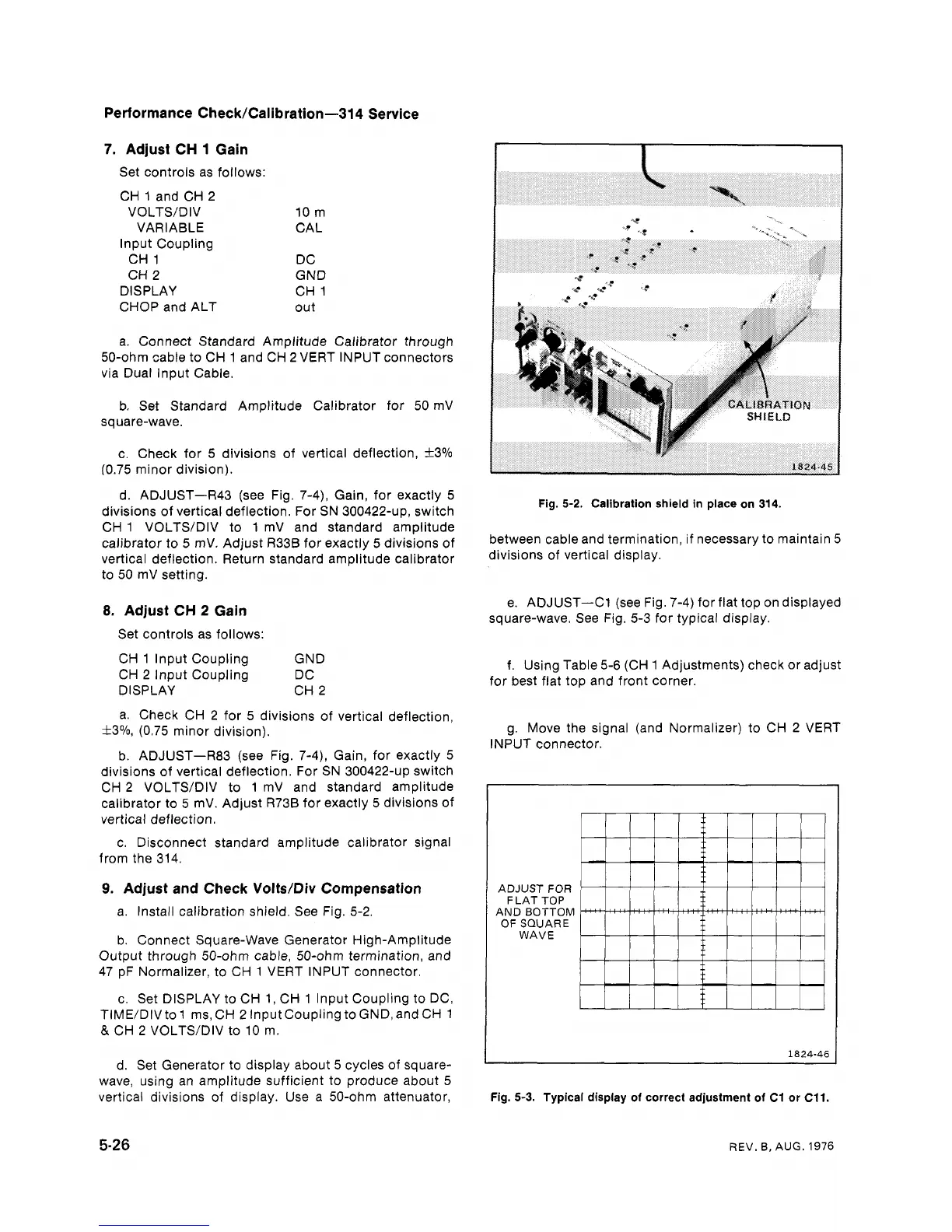
e.
ADJUST-C1 (see Fig. 7-4) for flat top on displayed
square-wave. See Fig. 5-3 for typical display.
f. Using Table 5-6 (CH 1 Adjustments) check or adjust
for best flat top and front corner.
g. Move the signal (and Normalizer) to CH 2 VERT
INPUT connector.
ADJUST
FOR
F
LAT TOP
AND BOTTOM
OF SQUARE
WAVE
c. Set DISPLAY to CH 1, CH 1 lnput Coupling to DC,
TIME/DIV to 1 ms, CH
2
lnput Coupling to GND, and CH 1
&
CH 2 VOLTS/DIV to 10 m.
d. Set Generator to display about 5 cycles of square-
wave, using an amplitude sufficient to produce about 5
vertical divisions of display. Use a 50-ohm attenuator,
--
Fig.
5-3.
Typical display of correct adjustment of
C1
or
C11.
REV.
B.
AUG. 1976
 Loading...


