Maintenance-314 Service
h. Disconnect the red, 6-pin connectorfrom P700on
H
V
&
Unblank circuit board.
i. Disconnect the black, single-pin connector from
P740 on H
V
&
Unblank circuit board.
j.
Disconnect the black 5-pin connector from P650 on
lnterface circuit board.
k. The power supply is now free of the body of the
instrument. To replace, reverse the foregoing procedure.
lnterface Board (Assembly A8)
a. Remove 8-pin connector from lnterface board (see
Fig. 4-5).
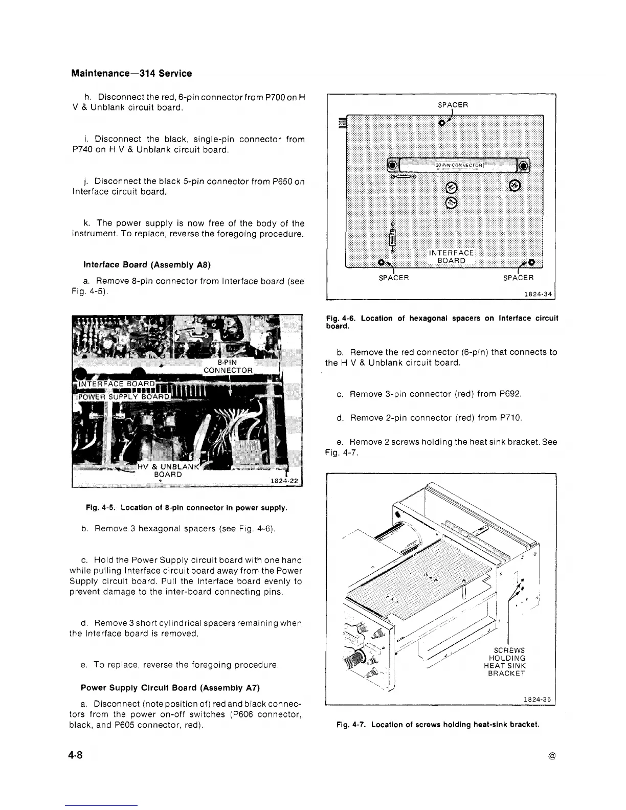
SPACER
I
Fig. 4-6. Location of hexagonal spacers on lnterface circuit
board.
b. Remove the red connector (6-pin) that connects to
the H
V
&
Unblank circuit board.
c. Remove 3-pin connector (red) from P692.
d. Remove 2-pin connector (red) from P710.
e. Remove 2 screws holding the heat sink bracket. See
Fig. 4-7.
I
Fig.
4-5.
Location
of
&pin connector in power supply.
b. Remove 3 hexagonal spacers (see Fig. 4-6).
c. Hold the Power Supply circuit board with one hand
while pulling lnterface circuit board away from the Power
Supply circuit board. Pull the lnterface board evenly to
prevent damage to the inter-board connecting pins.
d. Remove 3 short cylindrical spacers remaining when
the lnterface board is removed.
e. To replace, reverse the foregoing procedure.
Power Supply Circuit Board (Assembly A7)
a. Disconnect (note position of) red and black connec-
tors from the power on-off switches (P606 connector,
black, and P605 connector, red).
Fig.
4-7.
Location of screws holding heat-sink bracket.
 Loading...


