Maintenance-314 Service
e.
Carefully remove the crt base socket while pushing
the crt forward. When the socket has been removed, push
the
crt forward. Pull the crt from the shield. The
2-
conductor cable mentioned in part d comes out with the
crt.
Power Supply-High Voltage Section
a.
Remove 3-pin connector (white-brown, white-red,
white-orange) and two 2-pin connectors (white-blue,
white-green and white-brown, white-red) from corner of
the Interfacecircuit board (see Fig. 4-3A). Note wire colors
relative to the positions of board pins.
I
Fig.
4-3.
Location
of
connectors.
b.
Remove 2 screws holding the 30-pin connector to
chassis. See Fig. 4-4A.
c. Loosen socket-head screws on Focus and lntensity
control shafts at the insulated flexible connectors near the
controls. Loosen socket-head screw from the collar on the
lntensity control shaft.
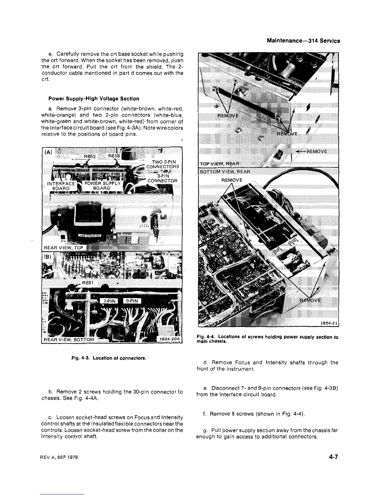
Fig.
4-4.
Locations
of
screws holding power supply section to
main chassis.
d. Remove Focus and lntensity shafts through the
front of the instrument.
e. Disconnect
7-
and 9-pin connectors (see Fig. 4-38)
from the Interface circuit board.
f. Remove
8
screws (shown in Fig. 4-4).
g. Pull power supply section away from thechassis far
enough to gain access to additional connectors.
REV
A,
SEP
1978
 Loading...


