Theory of Operation-314 Service
HIGH
VOLTAGE
I
REGULATOR
I-,
CHOP BLANK SIGNAL
-
GATE PULSE
(UNBLANKING SIGNAL)
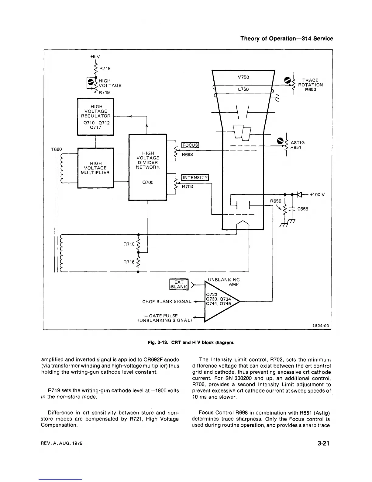
Fig.
3-13.
CRT
and
H
V
block
diagram.
amplified and inverted signal is applied to CR692F anode
(via transformer winding and high-voltage multiplier) thus
holding the writing-gun cathode level constant.
R719 sets the writing-gun cathode level at -1900 volts
in the non-store mode.
Difference in crt sensitivity between store and non-
store modes are compensated
by
R721, High Voltage
Compensation.
The Intensity Limit control,
R702, sets the minimum
difference voltage that can exist between the crt control
grid and cathode, thus preventing excessive crt cathode
current. For
SN
300200 and up, an additional control,
R706, provides a second lntensity Limit adjustment to
prevent excessive
crt cathode current at sweep speeds of
10 ms and slower.
Focus Control R698 in combination with R651 (Astig)
determines trace sharpness. Only the Focus control is
used during routine operation, and provides a sharp trace
REV.
A,
AUG.
1975
 Loading...


