Performance Check/Calibration-314 Service
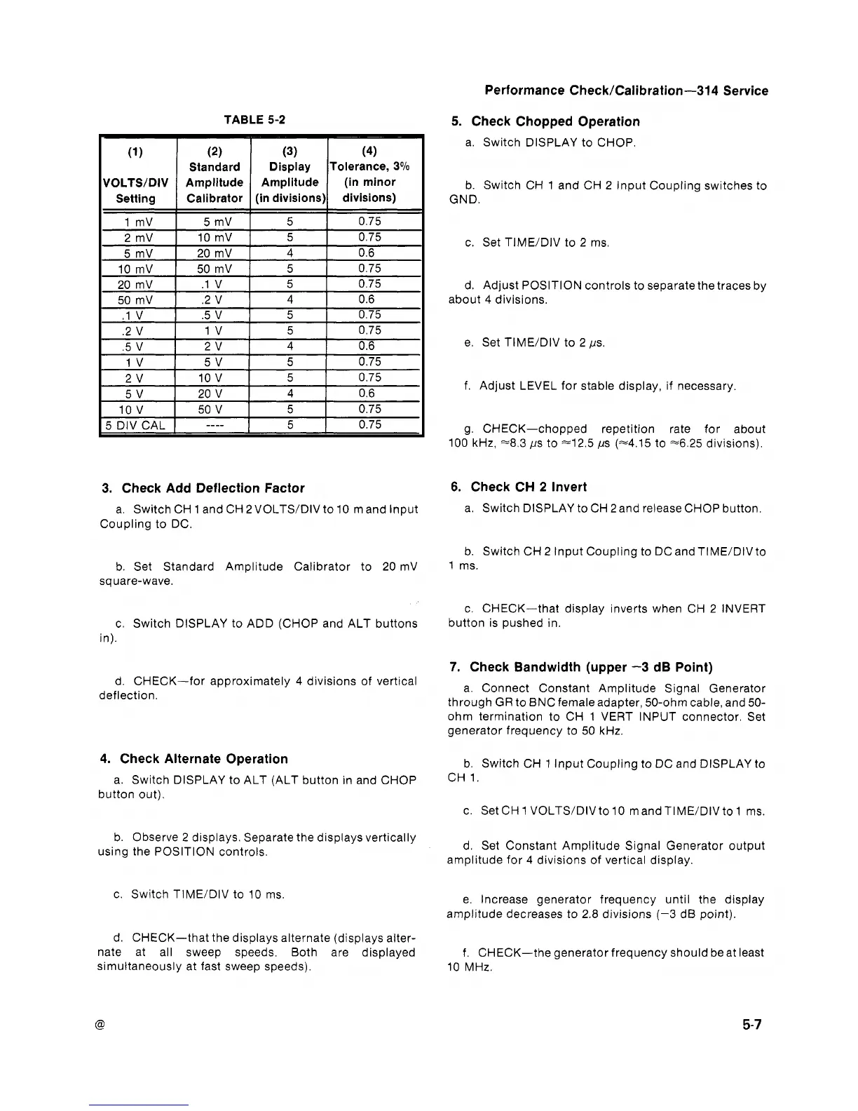
TABLE 5-2
(1
(2)
(3)
(4)
Standard Display Tolerance,
3%
VOLTS/DIV
Amplitude
Amplitude (in minor
Setting
Calibrator
(in divisions) divisions)
1 mV
5 mV 5 0.75
2 mV
10 mV 5 0.75
5 mV
20 mV 4 0.6
10
mV
50 mV 5 0.75
20
mV
.1 V
5
0.75
50
mV
.2 V 4 0.6
.-
-
-.
.
I
I
5
DIV CAL
1
----
I
5 0.75
3.
Check Add Deflection Factor
a. Switch CH
1
and CH 2VOLTS/DIV to 10 m and lnput
Coupling to DC.
b. Set Standard Amplitude Calibrator to 20 mV
sq uare-wave.
c. Switch DISPLAY to ADD (CHOP and ALT buttons
in).
d. CHECK-for approximately 4 divisions of vertical
deflection.
4. Check Alternate Operation
a. Switch DISPLAY to ALT (ALT button in and CHOP
button out).
b. Observe
2
displays. Separate the displays vertically
using the POSITION controls.
c. Switch TIME/DIV to 10 ms.
d.
CHECK-that the displays alternate (displays alter-
nate at all sweep speeds. Both are displayed
simultaneously at fast sweep speeds).
5.
Check Chopped Operation
a. Switch DISPLAY to CHOP.
b. Switch CH 1 and CH 2 lnput Coupling switches to
GND.
c. Set TIME/DIV to 2 ms.
d. Adjust POSITION controls to separatethe traces by
about 4 divisions.
e. Set
TIME/DIV to
2
ps
f. Adjust LEVEL for stable display, if necessary.
g. CHECK-chopped repetition rate for about
100 kHz,
~8.3 ps to 42.5 ps (~4.15 to ~6.25 divisions).
6.
Check CH
2
Invert
a. Switch DISPLAY to CH 2 and release CHOP button.
b. Switch CH 2 lnput Coupling to DC and TIME/DIV to
1 ms.
c. CHECK-that display inverts when CH 2 INVERT
button is pushed in.
7.
Check Bandwidth (upper
-3
dB Point)
a. Connect Constant Amplitude Signal Generator
through GR to BNC female adapter, 50-ohm cable, and 50-
ohm termination to CH 1 VERT INPUT connector. Set
generator frequency to 50 kHz.
b. Switch CH 1 lnput Coupling to DC and DISPLAY to
CH 1.
c. Set CH
1
VOLTS/DIV to 10 m and TIME/DIV to 1 ms.
d. Set Constant Amplitude Signal Generator output
amplitude for 4 divisions of vertical display.
e. Increase generator frequency until the display
amplitude decreases to 2.8 divisions (-3 dB point).
f.
CHECK-the generator frequency should beat least
10 MHz.
 Loading...


