Performance CheckICalibration-314 Service
HORIZONTAL
SYSTEM
Equipment Required
1. Time Mark Generator
1
2. Standard Amplitude Calibrator
3.
Function Generator
4.
50-ohm BNC Cable
5. 50-ohm Termination
Control Settings
INTENSITY
POWER
FOCUS
CH 1 and CH 2
VOLTS/DIV
VARIABLE
POSITION
Input Coupling
DISPLAY
CH 2 INVERT
TRIGGERING
LEVEL
SLOPE
Coupling
Source
Mode
TIME/DIV
Variable
Horizontal POSITION
SWEEP MAG
STORAGE
ST0 R
E
ENHANCE
AUTO ERASE
ENHANCE LEVEL
VIEWING TIME
EXT ATTEN (side panel)
Power Source
Line Voltage Selector
Regulating Range
midrange
0
n
midrange
.5
CAL
centered
DC
CH
1
out
centered
+
AC
I NT
AUTO
1 ms
CAL
midrange
X 1
out
out
out
CCW
CCW
1 X
AC
115 V
M
1.
Check
1
ms Timing
a. Apply 1 ms time markers from Time Mark Generator
output to CH 1 VERT INPUT connector via 50-ohm cable
and 50-ohm termination.
b. Set CH
1
VOLTS/DIV and VARIABLE for about 2
divisions of vertical display.
c. CHECK-for 1 time marker/division, t3% (t1.2
minor division) over the center
8
graticule divisions.
d. Turn TIME/DIV Variable fully counterclockwise.
e. CHECK-for 2.5, or more, markers/division.
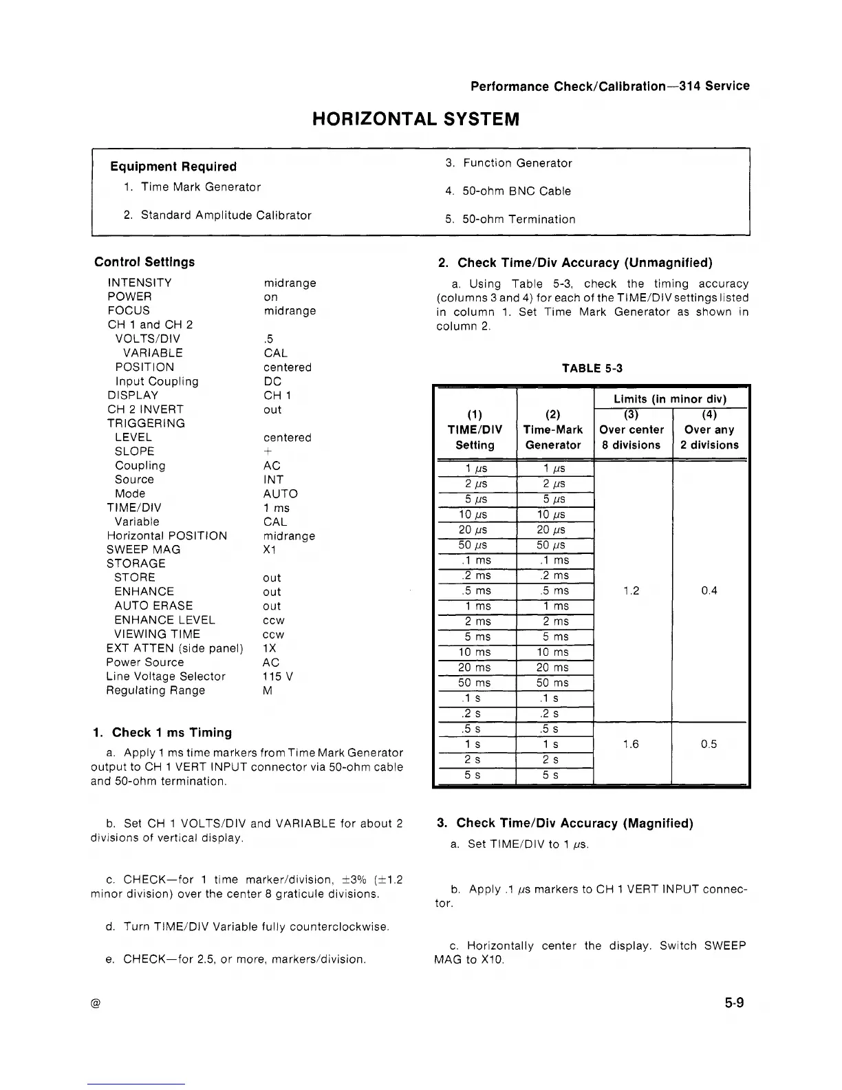
2. Check TimeIDiv Accuracy (Unmagnified)
a. Using Table 5-3, check the timing accuracy
(columns
3
and 4) for each of the TIME/DIV settings listed
in column 1. Set Time Mark Generator as shown in
column 2
TABLE
5-3
1
I
Limits (in minor div)
Over any
2
divisions
3. Check TimeIDiv Accuracy (Magnified)
a. Set TIME/DIV to 1 ,us.
b. Apply .1 ,us markers to CH 1 VERT INPUT connec-
tor.
c. Horizontally center the display. Switch SWEEP
MAG to
X10.
 Loading...


