EasyManuals Logo
Home>Tektronix>Inverter>AFG1000 Series

Tektronix AFG1000 Series User Manual

Tektronix AFG1000 Series
68 pages
To Next Page IconTo Next Page
To Previous Page IconTo Previous Page
Page #23 background imageLoading...
Page #23 background image
Getting started
AFG1000 Series Quick Start User Manual
13
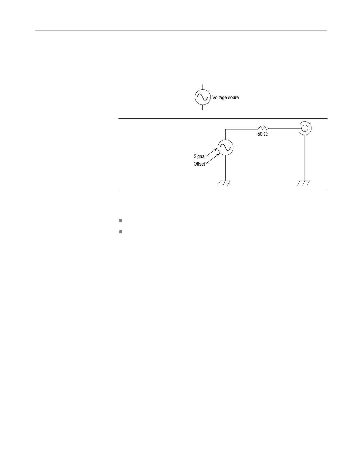
Equivalent output circuits
The following illustrations show the equivalent output circuits:
Legend for the following
images:
Output signals do not exceed
±10 V when the >50 Ω load
impedance is used.
A change to the load impedance (L) will affect the output window (maximum and
minimum levels) for a sine waveform as follows.
L = 50 : -5 V to +5 V (10 V
p-p
)
L = High Z: -10 V to +10 V (20 V
p-p
)

Other manuals for Tektronix AFG1000 Series

Questions and Answers:

Question and Answer IconNeed help?

Do you have a question about the Tektronix AFG1000 Series and is the answer not in the manual?

Tektronix AFG1000 Series Specifications

General IconGeneral
BrandTektronix
ModelAFG1000 Series
CategoryInverter
LanguageEnglish

Related product manuals