Instrument front panel, interface, and rear panel
AFG1000 Series Quick Start User Manual
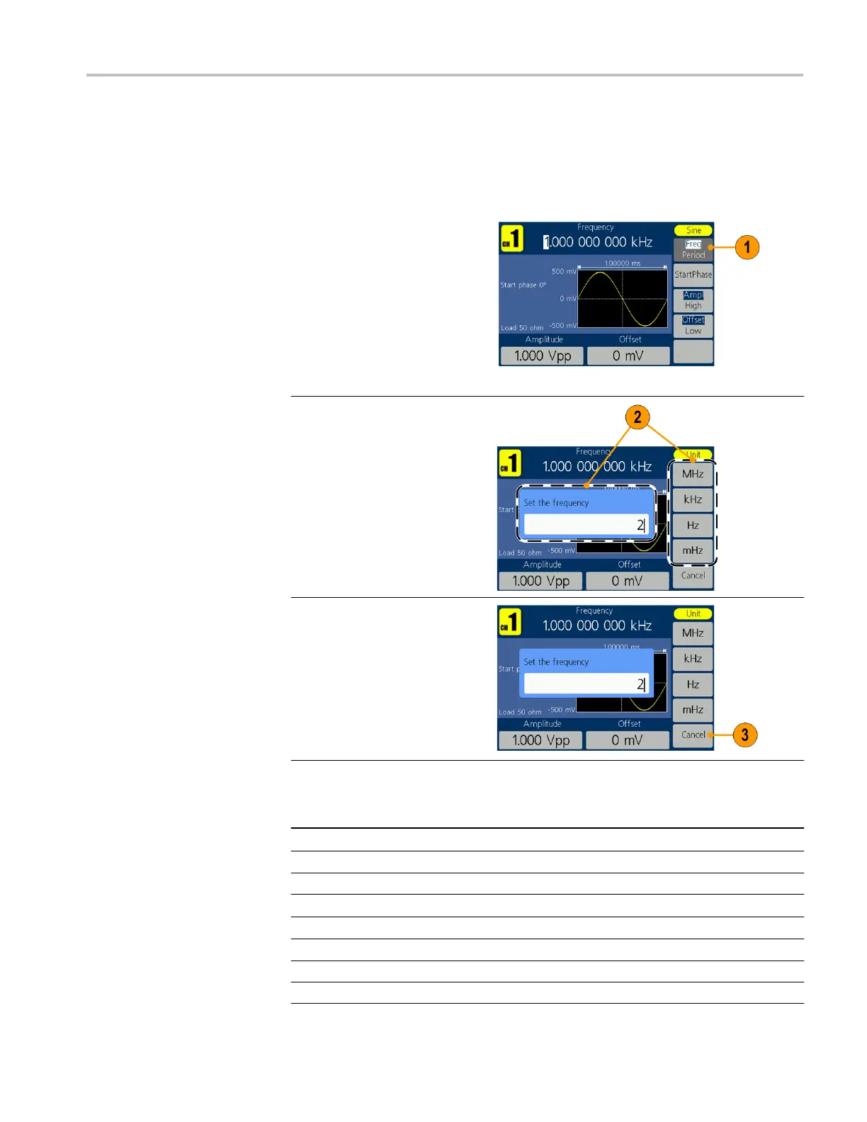
Adjust waveform parameters
When you turn on your instrument, the default output signal is a 1 kHz sine
waveform with an amplitude of 1 V
p-p
. In the following example, you can change
the frequency and amplitude of the original output signal.
1.
To change frequency,
press Freq/Period. Press
it again to choose Period.
The selected parameter
will be highlighted with a
white background. Use the
general purpose knob to
set frequency value
directly, and use the
◄ / ► direction button to
move the cursor.
2.
Or push the numeric
panel button, and an
input box will pop up.
Enter the frequency
value and choose the
proper unit. Use the
◄ BKSP panel button
to delete a character if
any input errors occur.
3.
Press Cancel to cancel
the operation.
NOTE: Change the Period,
Start Phase, Ampl, High,
Offset, and Low values in the
same way.
Unit conversions
The following conversion table shows the relationship between V
p-p
and V
rms
in the case of sine wave.
V
p-p
V
rms
dBm
10.00 V
p-p
3.54 V
rms
+23.98 dBm
2.828 V
p-p
1.00 V
rms
+13.01 dBm
2.000 V
p-p
707 mV
rms
+10.00 dBm
1.414 V
p-p
500 mV
rms
+6.99 dBm
632 mV
p-p
224 mV
rms
0.00 dBm
283 mV
p-p
100 mV
rms
-6.99 dBm
200 mV
p-p
70.7 mV
rms
-10.00 dBm
10.0 mV
p-p
3.54 mV
rms
-36.02 dBm
 Loading...


