Performance verification
AFG31000 Series Arbitrary Function Generator Specification and Performance Verification Technical Reference 41
2. Calculate the 50 Ω calibration factor (CF) from the reading value and record it, as shown in the
following table.
50 Ω calibration factor (Calibration factor (CF) = 2 / (1 + 50 Ω /
Measurement Ω) =)
Measurement (DMM reading) CF
Ω
Examples
50.50 Ω 1.0050 (= 2 / (1 + 50 / 50.50))
0.9962 (= 2 / (1 + 50 / 49.62))
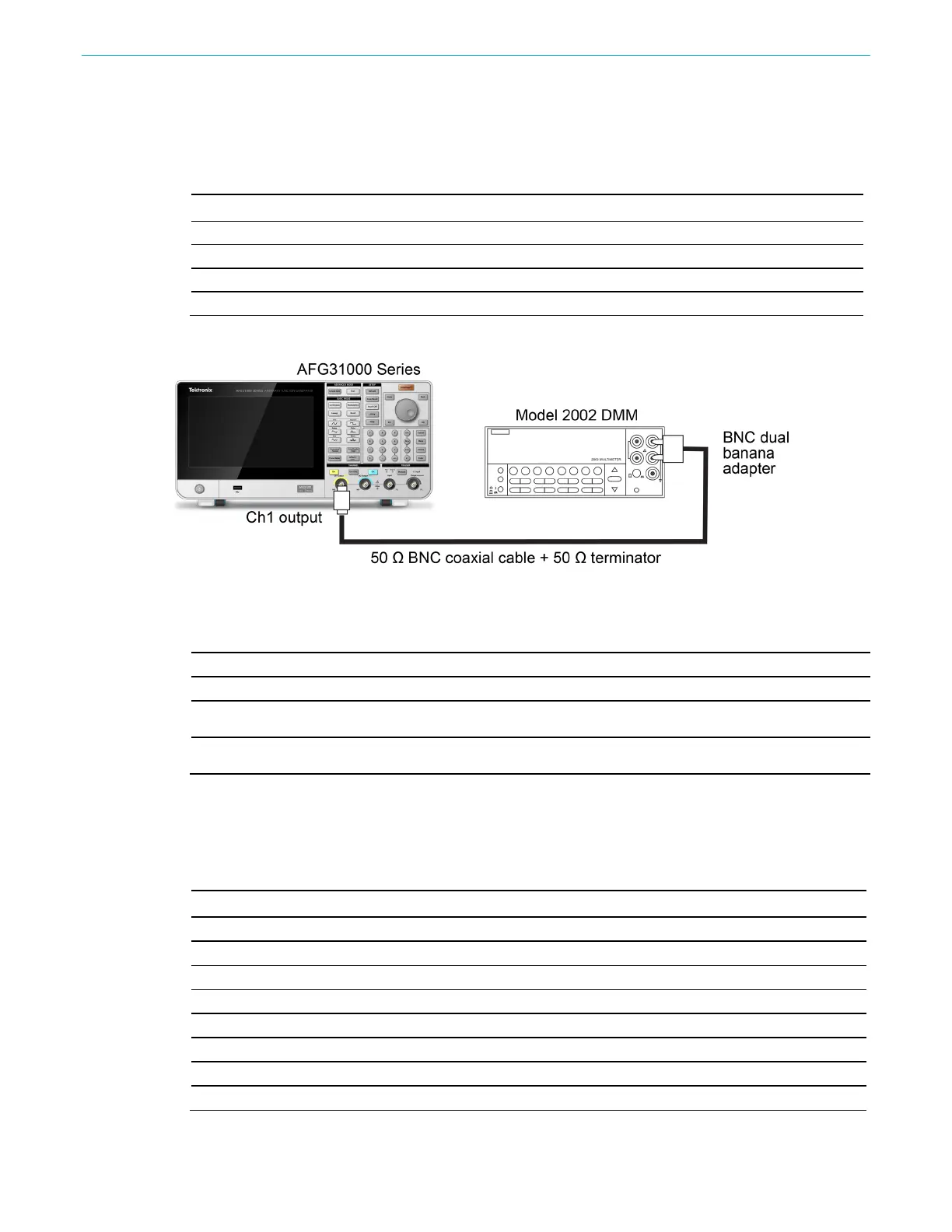
3. Connect the AFG31000 Series to the DMM as shown in the following figure. Be sure to connect
the 50 Ω terminator to the Ch1 (or Ch2) output connector on the AFG31000 Series.
Figure 7: Connections for the amplitude test
4. Set up the AFG31000 Series as shown in the following table.
Select menu Setting Operation
Function Sine Sine key (front panel)
Frequency/Period key (front panel)
Amplitude units Vrms Ch1 (or Ch2) menu > Amplitude/Level menu > Units > Vrms
Ch1 (or Ch2) Output On key (front panel)
5. Verify that each amplitude measurement is within the range specified for your AFG31000 Series
instrument in the following tables.
6. (Two-channel models only) Repeat steps 4 through 5 for channel 2 output.
Models AFG31021, AFG31022, AFG31051, AFG31052, AFG31101, and AFG31102
Function Frequency Amplitude Measurement Range
3.000 mV
rms
mV
rms
30.000 mV
rms
mV
rms
300.000 mV
rms
mV
rms
800.000 mV
rms
mV
rms
Sine 1.000 kHz
1.500 V
rms
V
rms
(1.500×CF±0.015) Vrms
2.000 V
rms
V
rms
2.500 V
rms
V
rms
3.500 V
rms
V
rms
 Loading...


