Rear Panel Features
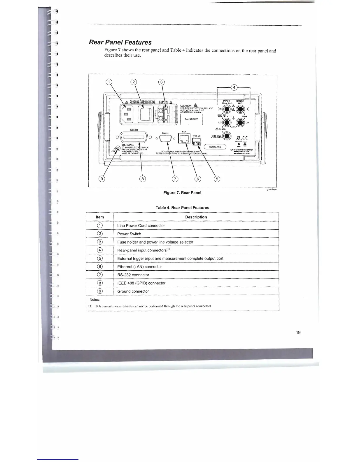
Figure 7 shows the rear panel and Table 4 indicates the connections on the rear panel and
describes their use.
r----i
4
}---.
CAUTION:
&.
FOR
FI
RE
PRO
TEC
TI
ON
REPLACE
ONL
Y W
IT
H A lSOV FUSE
AS
STA
TED
IN
MANUAl.
CAL
STICKER
LAN
SERIAL
lAG
)
gdcOS
eps
Figure
7.
Rear Panel
Table 4. Rear Panel Features
J
•
•
Item Description
CD
Line Power Cord connector
®
Power Switch
®
Fuse holder and power line voltage selector
8)
Rear-panel input connectors
f1
!
®
External trigger input and measurement complete output port
®
Ethernet (LAN) connector
(j)
RS-232 connector
®
IEEE 488 (GPIB) connector
®
Ground connector
Notes:
[I]
10 A current measurements can not be performed through the rear-panel connectors
19

 Loading...


