c. Hook up the test-signal source: Connect the output of the sine wave
generator to Ch 1 as shown in the following figure.
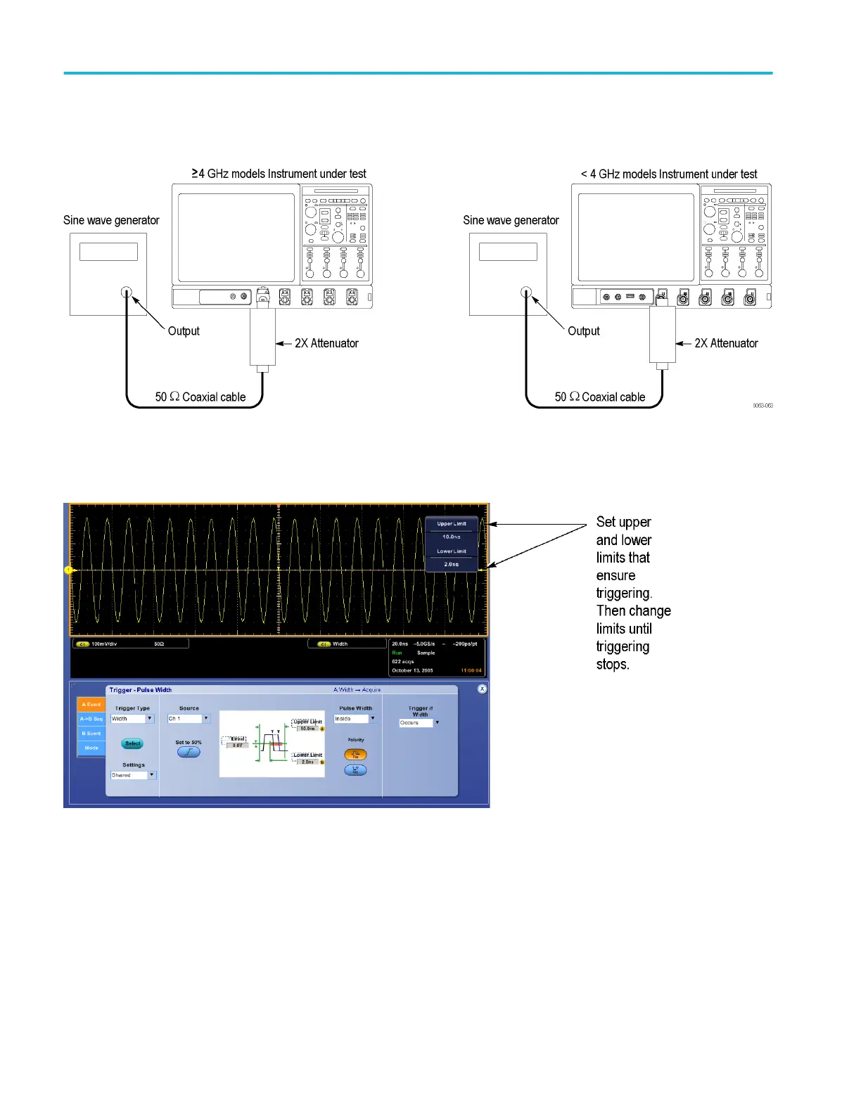
Figure 31: Time qualified trigger test hookup
d. Set the trigger mode: Press the Trigger Mode button to toggle it to
Normal.
Figure 32: Measurement of time accuracy for pulse and glitch triggering
2. Confirm the trigger system is within time-accuracy limits for time qualified
trigger accuracy (time range<1 μs):
a. Set upper and lower limits that ensure triggering at 100 MHz: (See
Figure 32: Measurement of time accuracy for pulse and glitch triggering
on page 254.)
■
Press the front-panel Advanced button and select the A Event tab;
then pull down on Trigger Type and select Width triggering.
■
Pull down Pulse Width and select Inside limits.
Performance verification (MSO/DPO70000C, MSO/DPO70000DX, and DPO7000C series)
254 MSO70000C/DX, DPO70000C/DX, DPO7000C, MSO5000/B, DPO5000/B Series
 Loading...


