Compensating the probe
Due to variations in oscilloscope input characteristics, the low-frequency
compensation of the probe may need adjustment after moving the probe from one
oscilloscope channel to another.
If a 1 kHz calibrated square wave displayed at 1 ms/division shows significant
differences between the leading and trailing edges, perform the following steps to
optimize low-frequency compensation:
1. Connect the probe to the oscilloscope channel that you plan to use for your
measurements.
2. Connect the probe to the probe compensation output terminals on the
oscilloscope front panel.
WARNING. To avoid electric shock, only connect to the Probe Comp signal on
the oscilloscope when making this adjustment.
3. Push Autoset or otherwise adjust your oscilloscope to display a stable
waveform.
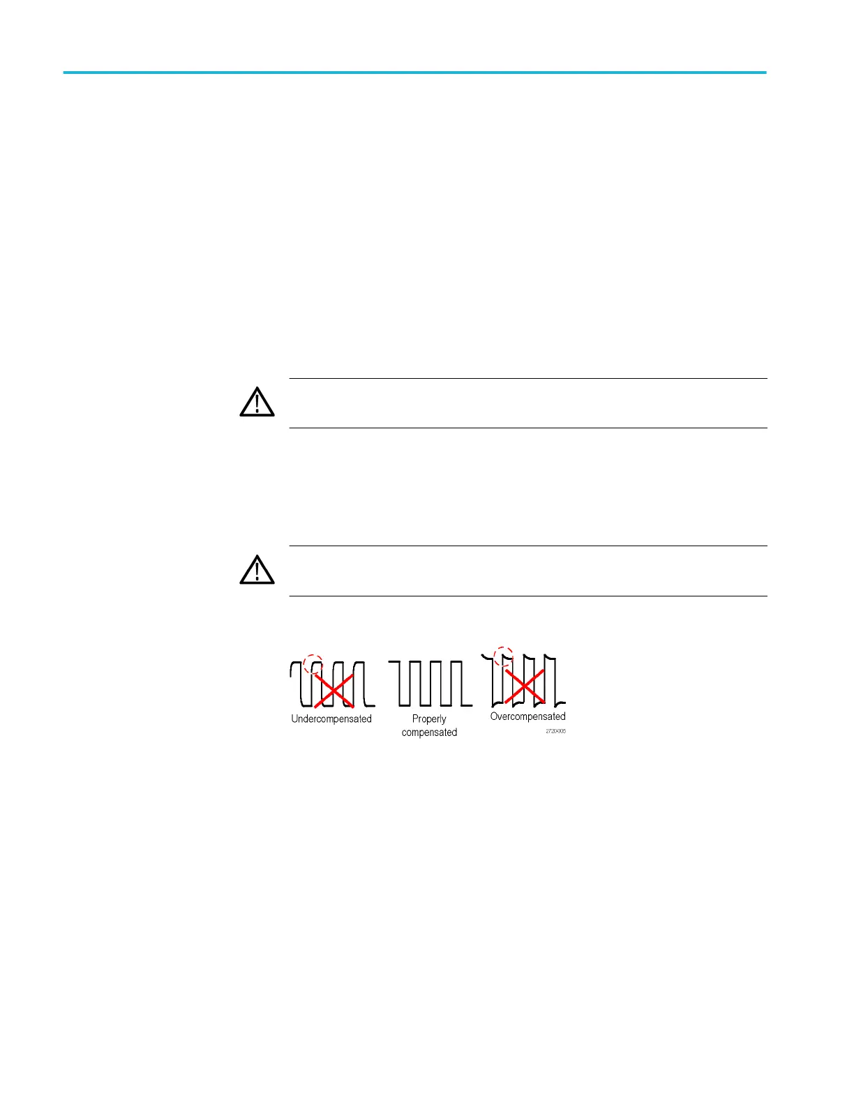
4. Adjust the trimmer in the probe until you see a perfectly flat-top square wave
on the display. (See illustration.)
WARNING.
To avoid electric shock, only use the insulated adjustment tool
when making compensation adjustments.
TPP0051 TPP0101 and TPP0201 series 10X passive probes information
124 TBS1000B and TBS1000B-EDU Series Oscilloscopes User Manual
 Loading...


